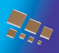
Sn-Pb Tanceram® Chip Capacitors
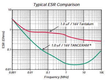
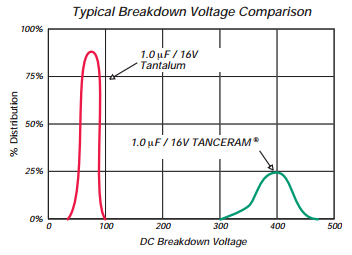
TANCERAM® chip capacitors can replace tantalum capacitors in many applications and offer several key advantages over traditional tantalums. Because Tanceram® capacitors exhibit extremely low ESR, equivalent circuit performance can often be achieved using considerably lower capacitance values. Low DC leakage reduces current drain, extending the battery life of portable products. Tancerams® high DC breakdown voltage ratings offer improved reliability and eliminate large voltage de-rating common when designing with tantalums.
Advantages:
- Low ESR
- Higher Surge Voltage
- DReduced CHIP Size
- Higher Insulation Resistance
- Low DC Leakage
- Non-polarized Devices
- Improved Reliability
- Higher Ripple Current
Applications:
- Switching Power Supply Smoothing (Input/Output)
- DC/DC Converter Smoothing (Input/Output)
- Backlighting Inverters
- General Digital Circuits
Technical Notes:
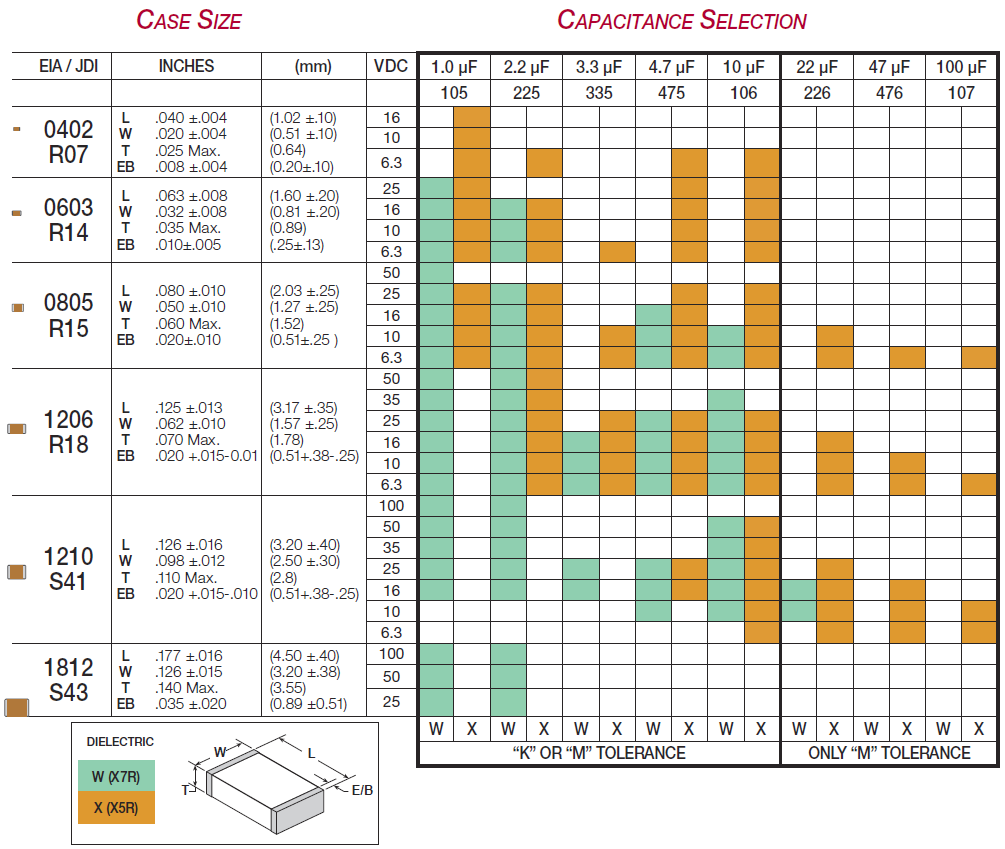
Capacitance Selection
Electrical Specifications
| X7R | X5R | |
|---|---|---|
| Temperature Coefficient: | ±15% (-55 to +125°C) | ±15% (-55 to +85°C) |
| Dissipation Factor: | For ≥ 50 VDC: 5% max. For ≤ 35 VDC: 10% max. |
For ≥ 50 VDC: 5% max. For ≤ 35 VDC: 10% max |
| Insulation Resistance (Min. @ 25°C, WVDC) |
100 ΩF or 10 GΩ, whichever is less | |
| Dielectric Strength: | 2.5 X WVDC, 25°C, 50mA max. | |
| Test Conditions: | Capacitance values ≤ 10 µF: 1.0kHz±50Hz @ 1.0±0.2 Vrms Capacitance values > 10 μF: 120Hz±10Hz @ 0.5V±0.1 Vrms |
|
How to Order