Ceramic Capacitor Aging Made Simple
Class II dielectrics experience a phenomenon called aging, and it is simply a decrease in capacitance over time due to crystalline changes that occur in all Class II dielectrics (X7R, X5R and Y5V). This is caused by the relaxation or realignment of the electrical dipoles within the capacitor. This phenomenon is affected by time, temperature, voltage (voltage has a minute effect).
As the relative “dielectric constant” or “εr” of the material increases, this effect is magnified. The εr of the material determines the volumetric capacity of the capacitor. As the εr increases we are able to design capacitors with higher capacitance values. These higher values have their drawbacks too. As the εr increases so does capacitor aging and capacitance loss in the capacitor due to temperature and voltage.
Class I dielectrics (NP0 – COG) do not exhibit this phenomenon as they are stable over Time, Temperature and voltage. The drawback for these dielectrics is that the εr is relatively low as compared to the Class II dielectrics. This means the maximum capacitance available in these stable parts is much lower than that of the Class II parts. Typically these εr are as follows: NP0 10-100, X7R 2000-5000 and Y5V can be as high as 25000.
The Effect of Time
The effect of time imposes a predictable loss of capacitance in Class II capacitors. For X7R and X5R the loss is calculated at -2.5% per decade hour and for Y5V it is -7% per decade hour. After manufacturing the crystalline structure of the dielectric material is reset. It is due to the realignment of these crystals after firing that the capacitor goes through a logarithmic loss of capacitance. The aging rate for each of these materials is listed below in Figure 1.
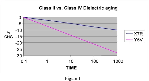
This aging rate is expressed in decade hours. This means after manufacturing the loss of capacitance is calculated at 1hr, 10hrs, 100hrs, 1000hrs etc….. This means at 10 hours the capacitance changes the same percentage as it will when measured at 100 hours and 1000 hours. As time goes on the aging process slows.
REVERSING THE AGING EFFECT
The aging process is reversible. By heating the capacitors over the “Curie Point” (approx 125c for Barium Titanate capacitors) the crystalline structure of the capacitor is returned to its original state and the capacitance value observed after manufacturing. This process is referred to as “De-Aging”. The amount of De-Aging is dependent on the level of temperature and how long the capacitors are exposed to it. Exposure to 150c for 1.5 hours is sufficient to return the capacitor to its original value. The soldering process is not necessarily an effective De-Aging process but the capacitance value will be raised.
STORAGE AND INSPECTION
It should be noted that the longer the capacitor is stored after manufacturing the lower the “Aged Capacitance” will be. This means that when the capacitor is inspected before assembly the capacitance may appear to be out of specified tolerance. This capacitance reading does not take into account the dielectric aging and the time since manufacturing. Only by De-Aging can the “Initial Capacitance” be verified.
IN-PLANT TESTING
In the manufacturing process the test limits are adjusted so that the capacitance value is within the specified tolerance at 1000hrs. This is critical as the capacitance change in the first 1000 hours is the greatest. After 1000 hours (41 days) the capacitor has gone through 4 decades of aging (0-1, 1-10, 10-100, 100-1000). This effect is different for each dielectric material as shown in Figure 1
TESTING AFTER ASSEMBLY
After the soldering process the capacitors have essentially been De-Aged. Capacitance measurements may be erratic in the initial 10 hours after testing. This is due to the initial capacitance value, dielectric type and the time between reflow and the capacitance measurement. For this reason it may be necessary to wait for the capacitance to stabilize after reflow before testing. In “High K” dielectrics the capacitance may also appear slightly high after the soldering process. This is normal as the capacitance is intended to be stable after 1000 hours so that there is adequate capacitance throughout the life of the circuit
Notice: Specifications are subject to change without notice. Contact your nearest Johanson Dielectrics, Inc. Sales Office for the latest specifications. All statements, information and data given herein are believed to be accurate and reliable, but are presented without guarantee, warranty, or responsibility of any kind, expressed or implied. Statements or suggestions concerning possible use of our products are made without representation or warranty that any such use is free of patent infringement and are not recommendations to infringe any patents. The user should not assume that all safety measures are indicated or that other measures may not be required. Specifications are typical and may not apply to all applications.