AC Power Computations for DC Rated Caps
Capacitors are usually rated in terms of DC voltage. This rating means that the part can be expected to operate reli-ably on a long-term basis at that DC voltage and at the capacitor's rated temperature. Since most applications include some AC voltage component, it is important to understand the factors which determine how much AC a given DC-rated part can withstand. These factors include frequency, voltage, power rating (size), capacitance value and the dielectric characteristics.
The effects of AC on capacitor characteristics and reliabil-ity depend partly on the type of dielectric used. For ceramic capacitors, the three primary dielectrics (NPO, X7R and Z5U) all have different characteristic changes with respect to applied AC. For example, with NPO dielectric, the values of capacitance and dissipation factor will remain rel-atively constant when various AC signals are applied. X7R, however, will exhibit small changes with the applied frequency and significant changes with the magnitude of voltage applied. Z5U will change even more with both frequency and voltage. The particular capacitor designs will affect the amount of change which will occur in these parameters, since they are dependent on both the dielectric used and on the thickness of that dielectric for a given voltage. These figures reference only the X7R dielectric. NPO will show no measurable changes with either voltage or frequency. Z5U will exhibit changes similar to X7R, but of much greater magnitudes. For this reason, Z5U is seldom used in AC applications.
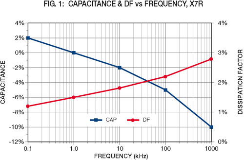
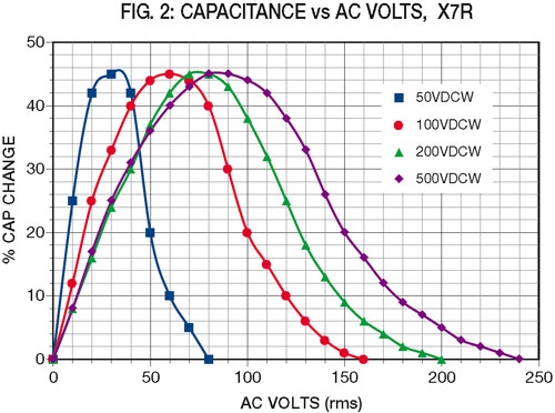
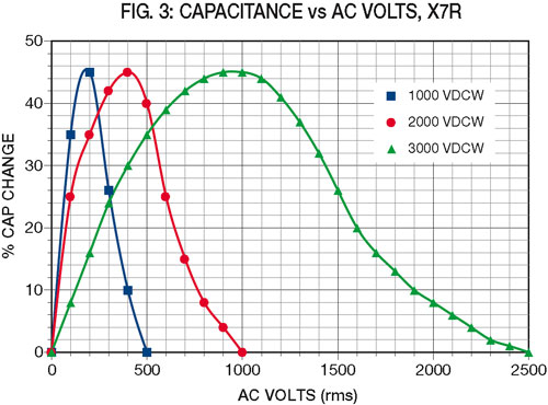
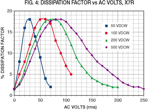
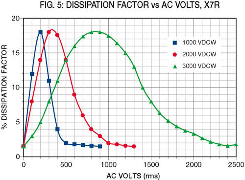
While the changes due to frequency can be easily charted for X7R (see Figure 1), those due to the voltage level depend upon the dielectric stress (volts per mil of dielectric thickness) and will be different for each voltage rating. Typical values for X7R are shown in Figures 2 through 5.
For a given application, the power dissipated in a capacitor can be calculated from the formula P=i² R, where P = the power in watts, i = the rms current through the capacitor and R = the Equivalent Series Resistance (ESR) of the capacitor. Then i= 2 pie fCE, where f = the frequency in Hertz, C= the capacitance in Farads and E = the rms voltage applied. Finally R= d/(2 pie fC), where d = the dissi-pation factor. Combining these three equations, the final power formula derived is P=2 pie fCE²d.
Now it is necessary to determine the values of capacitance and dissipation factor, assuming that we know the applied voltage and frequency. The capacitance can be determined from Figures 1, 2 and 3 by modifying the nominal capaci-tance by the changes shown for the given frequency and voltage stress. Dissipation factor can similarly be deter-mined from Figures 1, 4 and 5. Note that these values are typical and will vary from one manufacturer to another. The cap changes due to voltage can also be modified by the manufacturer to meet a given application requirement.
After the above corrections to capacitance and dissipation factor are made based upon the circuit voltage and fre-quency, the actual power consumption in the capacitor can be calculated from the formula P=2 pie fCE²d. Note that both the capacitance value and the frequency directly affect the power for a given voltage. This is why it is not possible to assign a generic AC rating (or a factor to apply to the DC rating) for capacitors. Only when these values are known (as in fixed value 60Hz power applications) can this be done.
Once the power is determined, it is necessary to find out whether a given capacitor will be able to withstand it. Johanson Dielectrics has developed a table of power ratings for various sizes of capacitors so this can be easily com-pared with the calculated power (see Table 1).
These power ratings are based upon a 25°C temperature rise as measured on the surface of the capacitor when power is applied. The ratings are also based on standard mounting on a PC board, no nearby heat sources and with no external coating or potting which could inhibit heat con-duction.
Here is an example: 0.1µF, 500V, X7R, 2520 size chip to be surface mounted and operated at 30Vrms and 10kHz. From the Johanson Dielectrics Catalog , select Johanson part number 501H47W104KV4. To use the formula P=2 pie fCE²d, the values of f (10,000) and E (30) are known, and the values of C and d must be determined from Figures 1 through 5.
Accordingly, the capacitance due to frequency changes –2% due to frequency (Figure 1) and +25% due to the voltage (use the 500VDC curve in Figure 2). This makes "C" the actual capacitance (.1)(.98)(1.25)=.123µF. Similarly, "d", the dissipation factor using the higher of the two values in Figures 1 and 4 is 8%(.08).
The values now are known:
f=10000
C=.123 (e-6)
E=30
d=.08
The calculated power is 0.56 watt. Referring to Table 1, the rated power for the H47 size is 1.3 watt so the design is valid for this application.
Applications Engineering assistance is available from the factory for other specific applications or questions.