Tanceram® Tantalum Replacement MLCs & ESR Curves
Historically, Tantalum capacitors have been used for smoothing and decoupling applications for switching power supplies, DC/DC converters, LCD drivers and general digital circuits. As the need grew for efficient power converters that operate at high frequencies, the design engineer needed components that dissipated less heat. For high frequency applications, a Tanceram®‚ chip capacitor is an excellent substitute for a Tantalum capacitor. Compared to a Tantalum capacitor, a Tanceram®‚ chip capacitor has a low ESR and low ESL at high frequencies. As a result, selecting a Tanceram®‚ capacitor with 1/2 to 1/10th the capacitance of a Tantalum will produce an impedance that is more than an order of magnitude lower than the Tantalum capacitor over the same high frequency range. The following example will compare the performance.
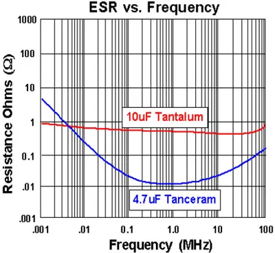
From 100 KHz to 70 MHz the typical 4.7µF Tanceram®‚ chip capacitor has a measured ESR from .05 to .02 Ohms while a typical 10µF Tantalum capacitor ESR measures from 1.2 to 0.8 Ohms. In this example, the Tanceram®‚ chip capacitor has a typical ESR that is 4% of the value of a comparable Tantalum capacitor over the frequency range of 100 KHz to 70 MHz (Figure 1).
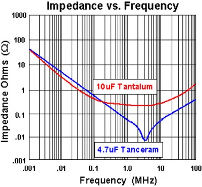
A typical 4.7uF Tanceram®‚ chip capacitor has low impedance from 100 KHz to 70 MHz. From Figure 2 the self-resonant frequency is approximately 3 MHz, for a remarkably low ESL of 600pH! Also, the lower impedance produces less heat in power conversion applications.
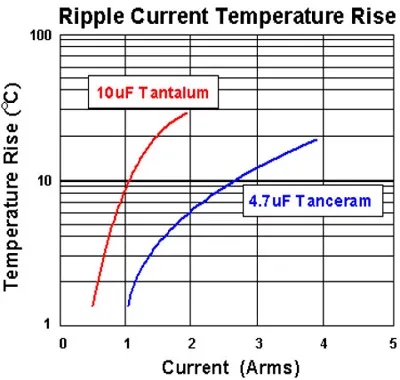
Figure 3 shows the temperature rise vs. ripple current. From the example capacitor values, a Tanceram®‚ chip capacitor can handle approximately 3 times the ripple current to produce a comparable temperature rise.
Often, substituting a Tanceram®‚ chip capacitor to replace a Tantalum capacitor will reduce the circuit size and cost while providing superior performance. The Tantalum substitution guide on page 2 was developed based on the principals discussed above.
Typical performance curves for popular Tanceram® parts can be found on page 3 and 4 of the PDF file.
Component Handling
Damage to large capacitors can also be caused by improper handling. AMC takes great care during the manufacturing processes to make sure that such damage does not occur. At the user's facility, it is equally important that careful handling be observed from receiving to stock to kitting and throughout the assembly and test.
For very large surface mount chips and especially the stacked Switch-Mode capacitors, additional precautions are necessary. From chip to final testing, the devices are kept separate from one another to prevent chipping and cracking. The packaging for shipment is in foam cushioned pockets especially designed for this purpose. The shipping containers should be utilized as much as possible to make sure that the capacitors cannot bump against each other. If ESD packages are used in kitting or storage, make sure that the capacitors are cushioned inside these packages. If a large capacitor is accidentally dropped on a hard surface, it should not be used even if it appears intact.
Notice: Specifications are subject to change without notice. Contact your nearest Johanson Dielectrics Sales Office for the latest specifications. All statements, information and data given herein are believed to be accurate and reliable, but are presented without guarantee, warranty, or responsibility of any kind, expressed or implied. Statements or suggestions concerning possible use of our products are made without representation or warranty that any such use is free of patent infringement and are not recommendations to infringe any patents. The user should not assume that all safety measures are indicated or that other measures may not be required. Specifications are typical and may not apply to all applications.