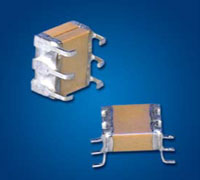
Mini-Switchmode® Capacitors
JDI's Mini-Switch Mode® ceramic capacitors combine the advantages of high capacitance found in tantalum capacitors with very low ESR performance of ceramic capacitors. The "J" and "L" lead configurations replace 1825 and 2225 SMT chips to provide stress relief and prevent cracking due to thermal cycling or mechanical board flexing. Another plus of the J-lead style is that this configuration allows use of the same solder lands as the SMT chips. See the Switch-Mode section for larger values. See also the Technical Notes on soldering and handling and suggested solder lands.
Key Features:
- Stress Relief from Cracking due to Thermal Cycling, TCE Mismatches or Board Flexing
- 25 to 500 VDC Ratings
- Custom Sizes, Voltages, and Values Available
- Ideal for DC-DC Power Supply Applications
General Specifications:
- Stress Relief from Cracking due to Thermal Cycling, TCE Mismatches or Board Flexing
- 25 to 500 VDC Ratings
- Custom Sizes, Voltages, and Values Available
- Ideal for DC-DC Power Supply Applications
Capacitance Values
| Size Code | EIA Chip Size | NP0 Max Capacitance (μF) | X7R Max Capacitance (μF) | ||||||||
|---|---|---|---|---|---|---|---|---|---|---|---|
| 25V | 50V | 100V | 200V | 500V | 25V | 50V | 100V | 200V | 500V | ||
| P09 | 1825 | 0.056 | 0.047 | 0.039 | 0.027 | 0.018 | 1.5 | 1.2 | 0.75 | 0.56 | 0.27 |
| P29 | 1825 | 0.11 | 0.094 | 0.078 | 0.054 | 0.036 | 3.0 | 2.4 | 1.5 | 1.1 | 0.54 |
| P39 | 1825 | 0.16 | 0.14 | 0.11 | 0.081 | 0.054 | 4.5 | 3.6 | 2.2 | 1.6 | 0.81 |
| P49 | 1825 | 0.22 | 0.18 | 0.15 | 0.10 | 0.007 | 6.0 | 4.8 | 3.0 | 2.2 | 1.0 |
| P08 | 2225 | 0.068 | 0.056 | 0.047 | 0.033 | 0.027 | 2.7 | 2.2 | 1.5 | 1.2 | 0.39 |
| P28 | 2225 | 0.13 | 0.11 | 0.094 | 0.066 | 0.054 | 5.4 | 4.4 | 3.0 | 2.4 | 0.78 |
| P38 | 2225 | 0.20 | 0.16 | 0.14 | 0.010 | 0.081 | 8.1 | 6.6 | 4.5 | 3.6 | 1.1 |
| P48 | 2225 | 0.27 | 0.22 | 0.18 | 0.13 | 0.10 | 10 | 8.8 | 6.0 | 4.8 | 1.5 |
Mechanical Specifications
| Dimensions Applicable to specific sizes: | 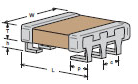 | 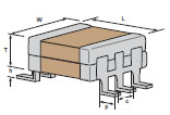 | 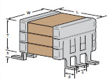 | 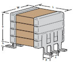 |
||||||||||||||
| in. | mm | |||||||||||||||||
| h ± .010 | .070 | 1.78 | ||||||||||||||||
| c Typ. | .100 | 2.54 | ||||||||||||||||
| p ± .015 | .065 | 1.65 | ||||||||||||||||
| Dimensions Applicable to specific sizes: | P08 | P09 | P28 | P29 | P38 | P39 | P48 | P49 | ||||||||||
| in. | mm | in. | mm | in. | mm | in. | mm | in. | mm | in. | mm | in. | mm | in. | mm | |||
| L max | .280 | 7.11 | 0.24 | 6.1 | 0.28 | 7.11 | 0.24 | 6.1 | 0.28 | 7.11 | 0.24 | 6.1 | 0.28 | 7.11 | 0.24 | 6.1 | ||
| W max | .270 | 6.86 | 0.27 | 6.86 | 0.27 | 6.86 | 0.27 | 6.86 | 0.27 | 6.86 | 0.27 | 6.86 | 0.27 | 6.86 | 0.27 | 6.86 | ||
| T max | 0.95 | 2.41 | 0.095 | 2.41 | 0.19 | 4.83 | 0.19 | 4.83 | 0.285 | 7.24 | 0.285 | 7.24 | 0.38 | 9.65 | 0.38 | 9.65 | ||
| Note: J-Lead and L-Lead options are available on all sizes above | ||||||||||||||||||
Electrical Specifications
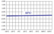
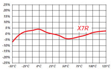
| X7R | NP0 | ||
| TEMPERATURE COEFFICIENT: | -55 to 125° | 0 ± 15% | 0 ± 30ppm/°C |
| DISSIPATION FACTOR: | 1kHz, 25°C | 2.5% max | 0.1% max |
| AGING RATE: | % per decade hour | 2.5% | none |
| INSULATION RESISTANCE: | 1000⟨F or 100G⟨, whichever is less at rated WVDC, 25°C | ||
| DIELECTRIC STRENGTH: | For 500V Ratings 750VDC, 25°C, 50mA max For 200V Ratings 2xWVDC, 25°C, 50mA max For 25-100V Ratings 2.5xWVDC, 25°C, 50mA max |
||
| CAP & D.F. MEASUREMENTS: | 1kHz ±50Hz; 1.0±0.2 VRMS, 25°C | ||
How to Order
Valid options are shown except for Capacitance
A typical PN is M2EH500W395K1J1001U. This part number breaks down as follows:
Capacitors SMPS P-Series PME - 2 chips, 2225, X7R, 50.0V, 3.90µF±10%, "J" Leads, 13" Reel Embossed Tape
New Johanson Global Part Number Breakdown
* Not all combinations create valid part numbers, ask our Apps Engineering Team for assistance creating a valid part number Request for assistanceClick below to see the new Global Part Number Reference Chart for this product
Legacy How to Order Information