Resistor Metal Element Shunts
RCS Series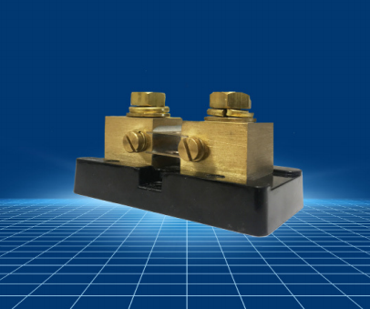
KEY FEATURES:
- Base Mounted Shunts. ( Non-Base Mounted Available)
- Manganin Resistive Element
- Current Rating 5 to 1200 Amps
- Rated Output 500mV, 100mV, or Custom
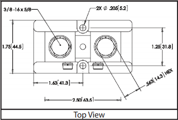
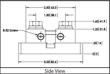
- DC Current Shunts - Sizes 2013, 3318
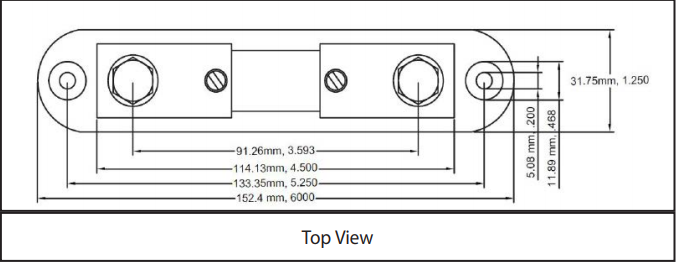
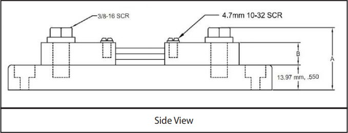
- DC Ammeter Shunts - Size 6013
APPLICATIONS:
- Electroplating
- Heavy Industry
- Battery Chargers
- Power Converters
- Solar Generators
- Wind Power
- Mining
- Current Measurements
| SIZE CODES | RATED CURRENT (A) | OPERATING CURRENT (A) | POWER RATING (W) | RESISTANCE (mΩ) 50mV Output | RESISTANCE (mΩ) 100mV Output | VOLTAGE TOLERANCE | OPERATING TEMPERATURE |
|---|---|---|---|---|---|---|---|
| 21 | 5-150 | 3.33-100 | 0.25-10 | 0.3333-10.00 | 0.6667-20.00 | ± 0.25% Standard ±0.1% Available |
-40 °C to+60°C |
| 32 | 170-600 | 113-400 | 10-50 | .833-.2941 | 0.1667-0.5882 | ||
| 61 | 1-500 | 0.667-333.33 | 0.25-40 | 0.10-50 | 0.20-100 | ± 0.1% Standard | 30°C+70°C |
Size 2013 - DC Current Shunts
Weight = 0.1
| Resistance (mΩ) | Power(W) | |||||
|---|---|---|---|---|---|---|
| Rated Current (A) | At 50mV Output | At 100mV Output | Opertating Current (A) |
At 50mV Output | At 100mV Output |
|
| RCS21 at 5 Amps | 5 | 10.00 | 20.00 | 3.33 | 0.25 | 0.5 |
| RCS21 at 10 Amps | 10 | 5.00 | 10.00 | 6.67 | 0.5 | 1 |
| RCS21 at 15 Amps | 15 | 3.333 | 6.667 | 10 | 0.75 | 1.5 |
| RCS21at 20 Amps | 20 | 2.500 | 5.000 | 13.3 | 1 | 2 |
| RCS21 at 30 Amps | 30 | 1.667 | 3.333 | 20 | 1.5 | 3 |
| RCS21 at 50 Amps | 50 | 1.000 | 2.000 | 33.3 | 2.5 | 5 |
| RCS21 at 75 Amps | 75 | 0.667 | 1.333 | 50 | 3.75 | 7.5 |
| RCS21 at 80 Amps | 80 | 0.625 | 1.250 | 53.3 | 4 | 8 |
| RCS21 at 85 Amps | 85 | 0.588 | 1.176 | 56.7 | 4.25 | 8.5 |
| RCS21 at 100 Amps | 100 | 0.500 | 1.000 | 66.7 | 5 | 10 |
| RCS21 at 150 Amps | 150 | 0.333 | 0.6667 | 100 | 7.5 | 15 |
Size 3318 - DC Current Shunts
Weight = 0.1
| Resistance (mΩ) | Power(W) | |||||
|---|---|---|---|---|---|---|
| Part Number | Rated Current (A) | Opertating Current (A) | At 50mV Output | At 100mV Output | At 50mV Output | At 100mV Output |
| RCS32 at 170 Amps | 170 | 113 | 0.2941 | 0.5882 | 8.5 | 17 |
| RCS32 at 200 Amps | 200 | 133 | 0.2500 | 0.5000 | 10 | 20 |
| RCS32 at 250 Amps | 250 | 166 | 0.2000 | 0.4000 | 12.5 | 25 |
| RCS32 at 300 Amps | 300 | 200 | 0.1667 | 0.3333 | 15 | 30 |
| RCS32 at 400 Amps | 400 | 267 | 0.1250 | 0.2500 | 20 | 40 |
| RCS32 at 450 Amps | 450 | 300 | 0.1111 | .2222 | 22.5 | 45 |
| RCS32 at 500 Amps | 500 | 333 | 0.1000 | 0.2000 | 25 | 50 |
| RCS32 at 600 Amps | 600 | 400 | 0.0833 | 0.1667 | 30 | 60 |
Size 6013 - DC Ammeter Shunts
Weight = 0.1
Note: No base not available on Size 6013
| Resistance (mΩ) | Power(W) | |||||
|---|---|---|---|---|---|---|
| Part Number | Rated Current (A) | Opertating Current (A) | At 50mV Output | At 100mV Ouput | At 50mV Output | At 100mV Output |
| RCS61B001B | 1 | .667 | 50 | 100 | 0.5 | 0.1 |
| RCS61B002B | 2 | 1.33 | 25 | 50 | .2 | .4 |
| RCS61B005B | 5 | 3.33 | 10 | 20 | .25 | .5 |
| RCS61B010B | 10 | 6.67 | 5.0 | 10 | .5 | 1 |
| RCS61B020B | 20 | 13.33 | 2.5 | 5.0 | 1 | 2 |
| RCS61B050B | 50 | 33.33 | 1.0 | 2.0 | 2.5 | 5 |
| RCS61B100B | 100 | 66.67 | 0.5 | 1.0 | 5 | 10 |
| RCS61B150B | 150 | 100 | 0.333 | 0.667 | 7.5 | 15 |
| RCS61B200B | 200 | 133.33 | 0.25 | 0.50 | 10 | 20 |
| RCS61B250B | 250 | 166.67 | 0.20 | 0.40 | 12.5 | 25 |
| RCS61B300B | 300 | 200 | 0.167 | 0.333 | 15 | 30 |
| RCS61B400B | 400 | 266.67 | 0.125 | 0.25 | 20 | 40 |
| RCS61B500B | 500 | 333.33 | 0.10 | 0.20 | 25 | 50 |
Technical Notes
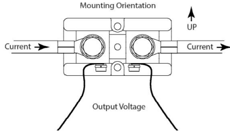
Mounting:
Shunts should be mounted with manganin resistive blades in a vertical position in order to promote the free convectional flow of air. If vertical mounting is not practical, forced air cooling or adding heat sinks to the blocks can reduce the operating temperature. The manganin blades must never exceed +145°C, otherwise permanent resistance change may occur.
When current of 100A or greater is passing through the shunt, the major portion of heat generated is dissipated by conduction through the shunt terminal blocks into the connecting buss bar or cable. Therefore, it is necessary to insure that good contact is made between the shunt terminal blocks and the conductor terminals and that the conductors have adequate cross section to keep the temperature of the shunt from exceeding 145°C ( 125°C recommended ).
If the shunt is mounted in an enclosure, care must be taken to ensure adequate cooling. If the power density is greater than 1/4 watt per square inch of the enclosure surface for all enclosed devices, additional cooling must be supplied in the form of air vents or fans.
Shunts also must be installed in a way that protects them from thermal expansion forces produced from buss bar or short-circuit forces. Flexible wiring may be required in high pulse current, high vibration, or high temperature applications.
Where possible, all shunts should be mounted on the ground side of the circuit. For circuits above 750VDC, RS shunts must be mounted on the ground side due to the dielectric strength of the shunt base.
Operating Current Derating:
For continuous operation, it is recommended that shunts are not run at more than two thirds (2/3) the rated current under normal conditions per IEEE standards for DC instrument shunts. At ambient temperatures above 40°C, the current must be further derated to prevent damage.
Pulse Operation:
Shunts that do not need continuous operation and are only exposed to intermittent pulses can be operated at levels above their rated current for short periods of times. Pulses are limited to the maximum temperature of the blades not exceeding 145°C ( 125°C recommended ). Many variables such as ambient temperature, cross section of the current carrying conductors, and pulse duration make calculating exact values diffi cult. Shunt size will need to be validated by customer for pulse current and duty cycle on a case by case basis.
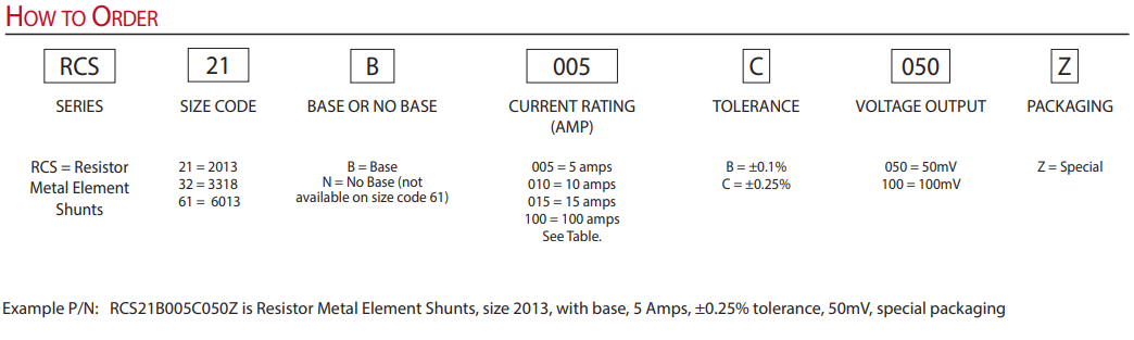
How to Order