High Voltage Radial Leaded Capacitors
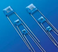
High Voltage Radial Leaded Capacitors for Power Supplies, Surge Protection, and Industrial Circuits
Features:
- Rated Working Voltages from 500 to 5,000 VDC
- Rugged Epoxy Coating Offers Increased Protection
- Compact MLC Designs Smaller Than Film or Disc
- DSCC Drawing & Other Screened Versions Available
- Custom Sizes, Voltages, and Values Available
Applications:
- Power Supplies
- Voltage Multipliers
- Data Isolation
- Surge Protection
- Industrial Control Circuits
- Custom Applications
Capacitance and Voltage Selection
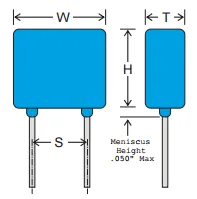
NOTE: Lead lengths are typically 1.25” for orders in bulk packaging. Leads are typically 1.00” for tape and reel packaging. Tape and reel packaging comes in 1000 piece reels.
| Case Size | RATED VOLTAGE | NP0 CAPACITANCE (MAX.) | X7R CAPACITANCE (MAX.) | |||||
|---|---|---|---|---|---|---|---|---|
| IN. | (MM) | VALUE | CODE | VALUE | CODE | |||
|
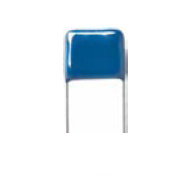
W | 0.250 max. | (6.35 max.) | 500 VDC | 4700 pF | 472 | .150 μF | 154 |
| H | 0.220 max. | (5.59 max.) | 1000 VDC | 1500 pF | 152 | .055 μF | 553 | |
| T | 0.270 max | (6.86 nom.) | 2000 VDC | 680 pF | 681 | 9000 pF | 902 | |
| S | 0.170 ±0.03 | (4.32 ±0.76) | 3000 VDC | 330 pF | 331 | 2800 pF | 282 | |
| DM / 1515 | LD | 0.025 ±.002 | (0.64 ±0.05) | 4000 VDC | 150 pF | 151 | 630 pF | 631 |
| 5000 VDC | 100 pF | 101 | 550 pF | 531 | ||||
|
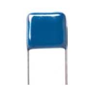
W | 0.370 max. | (9.40 max.) | 500 VDC | .022 μF | 223 | .480 μF | 484 |
| H | 0.300 max. | (7.62 max.) | 1000 VDC | 3300 pF | 332 | .170 μF | 174 | |
| T | 0.270 max. | (6.86 max.) | 2000 VDC | 1500 pF | 152 | .025 μF | 253 | |
| S | 0.275 ±0.03 | (6.99 ±0.76) | 3000 VDC | 680 pF | 681 | .011 μF | 113 | |
| ER / 2520 | LD | 0.025 ±.002 | (0.64 ±0.05) | 4000 VDC | 330 pF | 331 | 1800 pF | 182 |
| 5000 VDC | 220 pF | 221 | 940 pF | 941 | ||||
|
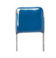
W | 0.470 max | (12.0 max.) | 500 VDC | .056 μF | 563 | 1.20 μF | 125 |
| H | 0.400 max. | (10.2 max.) | 1000 VDC | 4700 pF | 472 | .450 μF | 454 | |
| T | 0.320 max. | (8.13 max.) | 2000 VDC | 3300 pF | 332 | .094 μF | 943 | |
| S | 0.375 ±0.03 | (9.53 ±0.76) | 3000 VDC | 1500 pF | 152 | .043 μF | 433 | |
| FH / 3530 | LD | 0.025 ±.002 | (0.64 ±0.05) | 4000 VDC | 1000 pF | 102 | .010 μF | 103 |
| 5000 VDC | 470 pF | 471 | 4900 pF | 492 | ||||
|
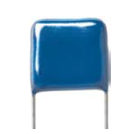
W | 0.570 max. | (14.5 max.) | 500 VDC | .100 μF | 104 | 2.20 μF | 225 |
| H | 0.500 max. | (12.7 max.) | 1000 VDC | .010 μF | 103 | .804 μF | 804 | |
| T | 0.320 max. | (8.13 max.) | 2000 VDC | 6800 pF | 682 | .240 μF | 244 | |
| S | 0.475 ±0.03 | (12.1 ±0.76) | 3000 VDC | 3300 pF | 332 | .073 μF | 733 | |
| GF / 4540 | LD | 0.025 ±.002 | (0.64 ±0.05) | 4000 VDC | 2200 pF | 222 | .028 μF | 283 |
| 5000 VDC | 1000 pF | 102 | .013 μF | 133 | ||||
|
W | 0.670 max. | (17.0 max.) | 500 VDC | .150 μF | 154 | 3.30 μF | 335 |
| H | 0.600 max. | (15.2 max.) | 1000 VDC | .015 μF | 153 | 1.20 μF | 125 | |
| T | 0.320 max. | (8.13 max.) | 2000 VDC | .010 μF | 103 | .440 μF | 444 | |
| S | 0.575 ±0.03 | (14.6 ±0.76) | 3000 VDC | 4700 pF | 472 | 0.130 μF | 134 | |
| HP | LD | 0.025 ±.002 | (0.64 ±0.05) | 4000 VDC | 3300 pF | 332 | .041 μF | 413 |
| 5000 VDC | 2200 pF | 222 | .020 μF | 203 | ||||
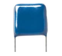
|
W | 0.770 max. | (19.6 max.) | 500 VDC | .220 μF | 224 | 5.70 μF | 575 |
| H | 0.720 max. | (18.3 max.) | 1000 VDC | .022 μF | 223 | 2.10 μF | 215 | |
| T | 0.320 max. | (8.13 max.) | 2000 VDC | .015 μF | 153 | .620 μF | 624 | |
| S | 0.675 ±0.03 | (17.1 ±0.76) | 3000 VDC | 6800 pF | 682 | .190 μF | 194 | |
| JF / 6560 | LD | 0.025 ±.002 | (0.64 ±0.05) | 4000 VDC | 4700 pF | 472 | .054 μF | 543 |
| 5000 VDC | 3300 pF | 332 | .026 μF | 263 | ||||
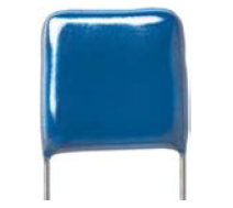
|
W | 0.870 max. | (22.1 max.) | 500 VDC | .330 μF | 334 | 7.30 μF | 735 |
| H | 0.750 max. | (19.1 max.) | 1000 VDC | .100 μF | 104 | 2.80 μF | 285 | |
| T | 0.320 max. | (8.13 max.) | 2000 VDC | .056 μF | 563 | .800 μF | 804 | |
| S | 0.775 ±0.03 | (19.7 ±0.76) | 3000 VDC | .033 μF | 333 | .250 μF | 254 | |
| KF/ 7565 | LD | 0.025 ±.002 | (0.64 ±0.05) | 4000 VDC | .010 μF | 103 | .080 μF | 803 |
| 5000 VDC | 6800 pF | 682 | .041 μF | 413 | ||||
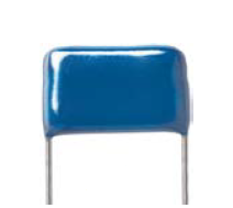
|
W | 1.450 max. | (36.8 max.) | 500 VDC | .470 μF | 474 | 12.0 μF | 126 |
| H | 0.720 max. | (18.3 max.) | 1000 VDC | .150 μF | 154 | 4.60 μF | 465 | |
| T | 0.320 max. | (8.13 max.) | 2000 VDC | .082 μF | 823 | 1.20 μF | 125 | |
| S | 1.375 ±0.03 | (34.9 ±0.76) | 3000 VDC | .047 μF | 473 | .390 μF | 394 | |
| MK / 13060 | LD | 0.025 ±.002 | (.064 ±0.05) | 4000 VDC | .015 μF | 153 | .130 μF | 134 |
| 5000 VDC | .010 μF | 103 | .068 μF | 683 | ||||
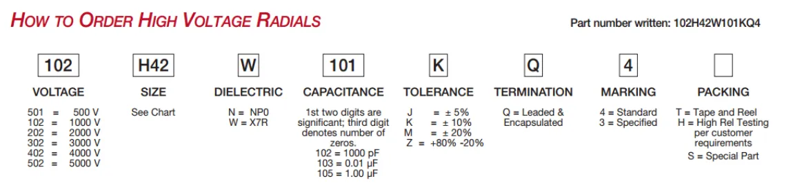
How to Order
Valid options are shown except for Capacitance
A typical PN is RLDM102G102J3QN001T. This part number breaks down as follows:
Capacitors BME MiniSM - 1 chip, 2220, X7R, 50V, 10µF±20%, "J" Leads, Bulk
New Johanson Global Part Number Breakdown
* Not all combinations create valid part numbers, ask our Apps Engineering Team for assistance creating a valid part number Request for assistanceClick below to see the new Global Part Number Reference Chart for this product
The legacy info below is for reference only.
Johanson has instituted a new Global Part Numbering (GPN) system.
Only the part number is changing. The parts are produced with the exact same materials, manufacturing processes, manufacturing controls, dimensions, physical attributes and testing as the parts supplied with the legacy part numbers.
The GPNs will be phased in over the next several years and are planned to be completed by January 1, 2026.
We will continue to quote and accept orders with the current (legacy) part numbers throughout this period.
Beginning January 1, 2022, all samples will be provided with the GPN.
Updates associated with this change will occur periodically.
A database for the approximate 2 million crosses can be accessed at: https://www.johansontechnology.com/pn-search