Product Range Summary
| SIZE CODE | INDUCTANCE RANGE | RATED CURRENT RANGE
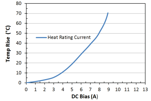
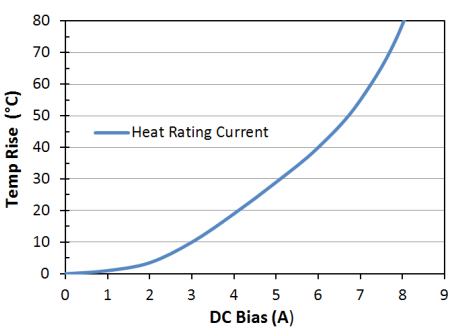
Based on Inductance Change | RATED CURRENT RANGE
Based on Temperature Rise | DC RESISTANCE RANGE | OPERTING 1
TEMPERTURE RANGE |
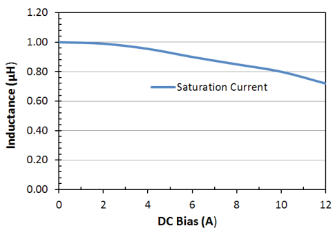
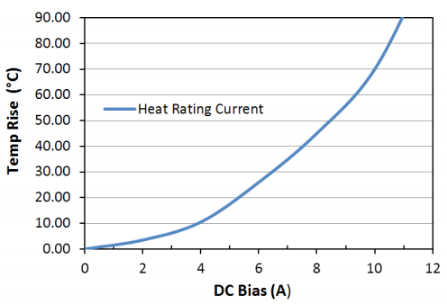
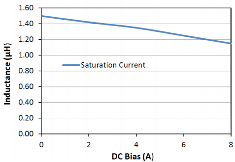
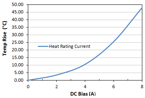
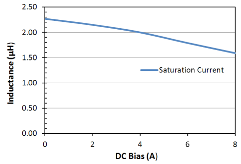
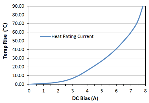
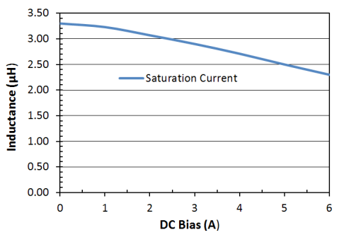
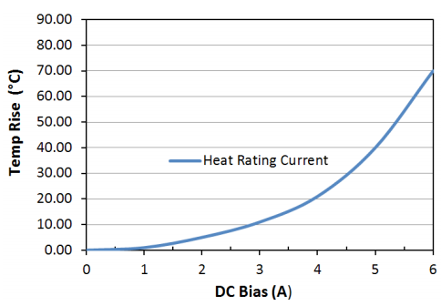
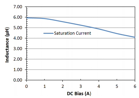
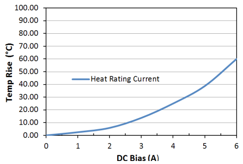
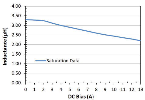
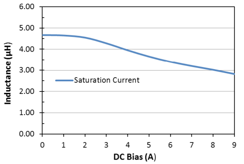
| 2410 | 0.68 - 22.0 μH | 0.40 - 2.60 A | 0.40 - 2.50 A | 60 mΩ - 1470 mΩ | |
| 3010 | 1.00 - 100.0 μH | 0.15 - 2.30 A | 0.18 - 2.30 A | 50 mΩ - 5.00 Ω | -40ºC to +125ºC |
| 3012 | 1.00 - 47.0 μH | 0.23 - 1.90 A | 0.35 - 1.71 A | 45 mΩ - 1250 mΩ |
| 3015 | 1.00 - 100.0 μH | 0.25 - 2.30 A | 0.30 - 2.30 A | 28 mΩ - 2100 mΩ |
| 4018 | 0.82 - 220.0 μH | 0.30 - 4.70 A | 0.28 - 4.00 A | 16 mΩ - 2960 mΩ |
| 4025 | 1.00 - 220.0 μH | 0.20 - 3.00 A | 0.20 - 3.00 A | 12 mΩ - 2300 mΩ |
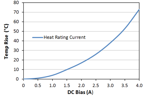
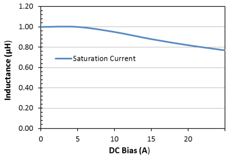
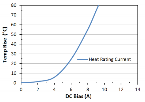
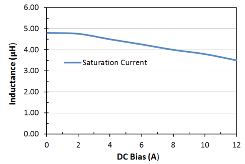
| 5040 | 1.50 - 47.0 μH | 1.10 - 6.00 A | 0.90 - 3.60 A | 15 mΩ - 270 mΩ |
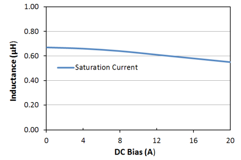
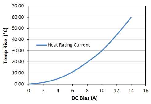
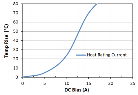
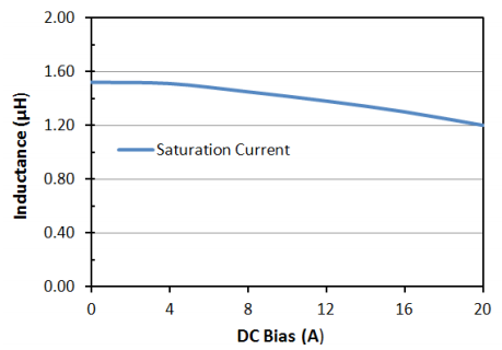
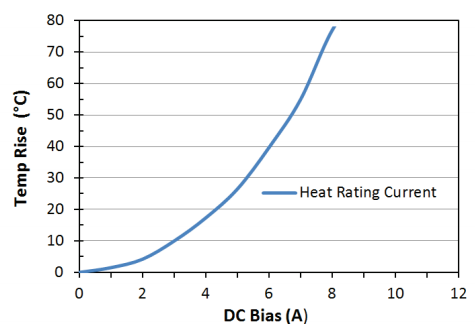
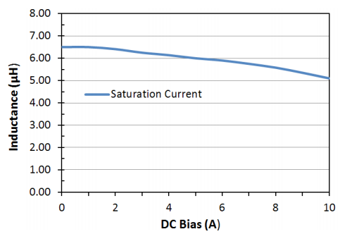
| 6045 | 1.00 - 220.0 μH | 0.55 - 8.60 A | 0.50 - 6.50 A | 10 mΩ - 920 mΩ |
| Consult Factory for values not listed in the product range |
1 Including self-generated heat |
TEST FREQUENCY: 100KHz, 1V
STORAGE TEMPERATURE: -10ºC to +40ºC, humidity 30 to 70% R.H.
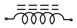
MOISTURE SENSITIVITY LEVEL: MSL - 1 | Electrical Schematic: No Polarity
 |
2410
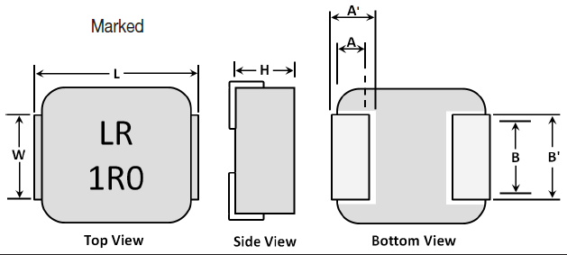
| Units | Inches | mm |
Not marked 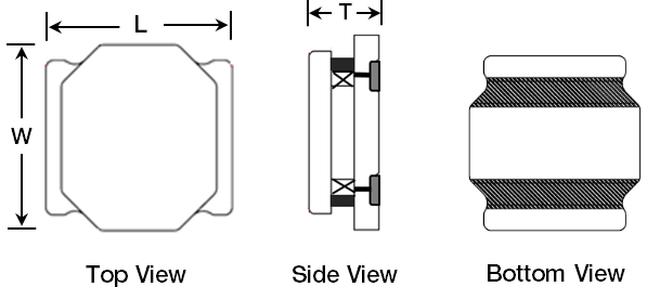 |
L | 0.094
±0.004 | 2.40
±0.10 |
| W | 0.094
±0.004 | 2.40
±0.10 |
T
max | 0.039 | 1.00 |
| | Part | Material | 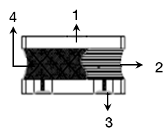 |
| 1 | Ferrite Core | Ni-Zn Ferrite |
| 2 | Copper Wire | Cu / P180 Grd 1 |
| 3 | Termination | Ag / Ni / Sn |
4 | Adhesive | Silicon Base Resin |
| Magnetic Powder | Ni-Zn Ferrite |
| Part Number | Inductance
@ 100KHz, 1V | Rated Current Based *1
on Inductance Change | Rated Current Based *2
on Temperature Rise | DC
Resistance | DC Resistance
Tolerance |
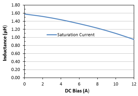
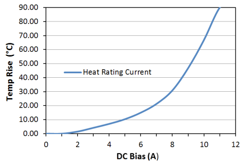
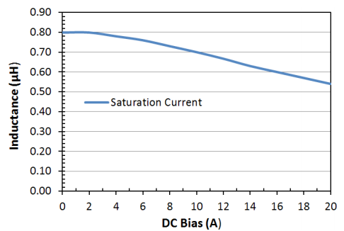
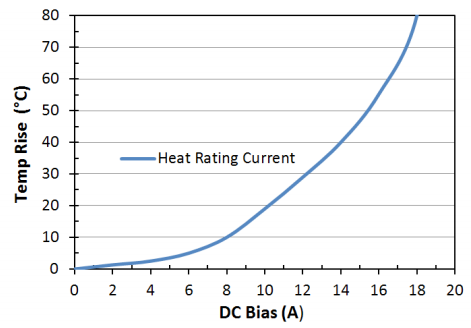
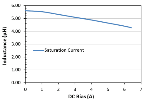
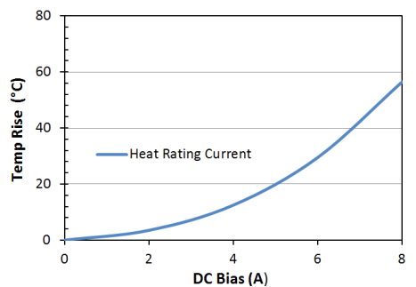
| LPC2410R68NE | 0.68 μH, ±30% | 2.60 A | 2.50 A | 60 mΩ | ±30% |
| LPC24101R0NE | 1.0 μH, ±30% | 2.00 A | 1.90 A | 70 mΩ | ±30% |
| LPC24101R5ME | 1.5 μH, ±20% | 1.50 A | 1.50 A | 110 mΩ | ±20% |
| LPC24102R2ME | 2.2 μH, ±20% | 1.30 A | 1.20 A | 140 mΩ | ±20% |
| LPC24103R3ME | 3.3 μH, ±20% | 1.05 A | 1.00 A | 220 mΩ | ±20% |
| LPC24104R7ME | 4.7 μH, ±20% | 0.92 A | 0.90 A | 290 mΩ | ±20% |
| LPC24106R8ME | 6.8 μH, ±20% | 0.75 A | 0.65 A | 410 mΩ | ±20% |
| LPC2410100ME | 10.0 μH, ±20% | 0.60 A | 0.55 A | 690 mΩ | ±20% |
| LPC2410150ME | 15.0 μH, ±20% | 0.50 A | 0.45 A | 1020 mΩ | ±20% |
| LPC2410220ME | 22.0 μH, ±20% | 0.50 A | 0.45 A | 1020 mΩ | ±20% |
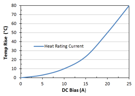
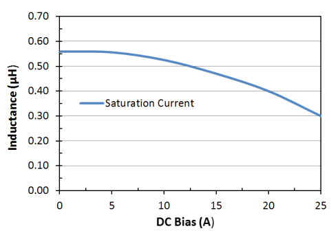
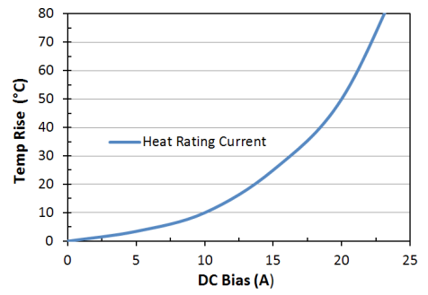
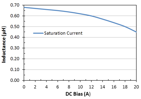
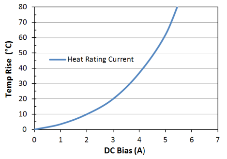
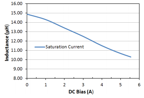
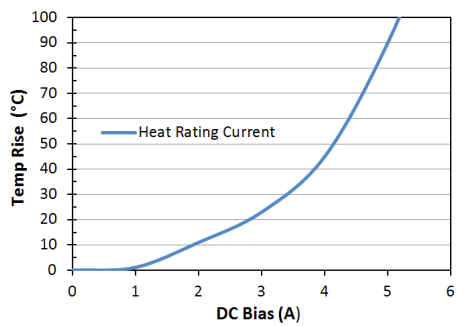
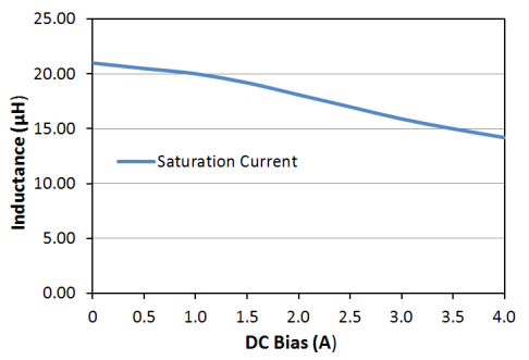
*1. Idc1: Based on inductance change (△L/Lo: -30%
*2. Idc2: Based on temperature rise (△T: 40ºC TYP.)
3010
| Units | Inches | mm |
Not marked |
L | 0.118
±0.004 | 3.00
±0.10 |
| W | 0.118
±0.004 | 3.00
±0.10 |
T
max | 0.039 | 1.00 |
| Part | Material | |
| 1 | Ferrite Core | Ni-Zn Ferrite |
| 2 | Copper Wire | Cu / P180 Grd 1 |
| 3 | Termination | Ag / Ni / Sn |
| 4 | Adhesive | Silicon Base Resin |
| Magnetic Powder | Ni-Zn Ferrite |
| Part Number | Inductance
@ 100KHz, 1V | Rated Current Based *1
on Inductance Change | Rated Current Based *2
on Temperature Rise | DC
Resistance | DC Resistance
Tolerance |
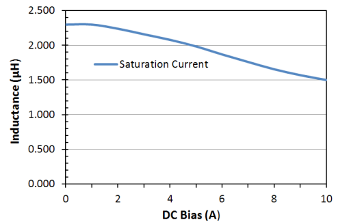
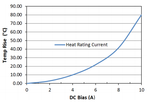
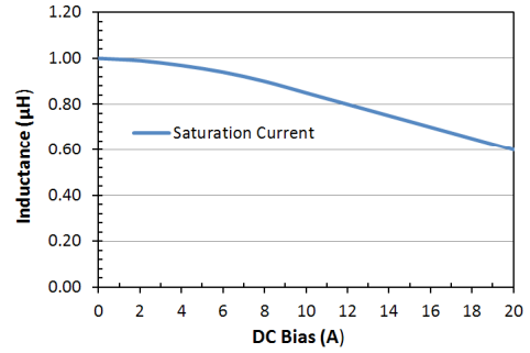
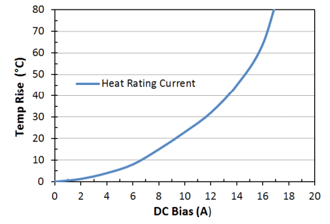
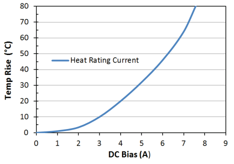
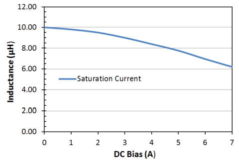
| LPC30101R0NE | 1.0 μH, ±30% | 2.30 A | 2.30 A | 50 mΩ | ±25% |
| LPC30101R2NE | 1.2 μH, ±30% | 2.10 A | 2.10 A | 62 mΩ | ±30% |
| LPC30101R5NE | 1.5 μH, ±30% | 1.90 A | 2.00 A | 70 mΩ | ±30% |
| LPC30102R2ME | 2.2 μH, ±20% | 1.80 A | 1.90 A | 80 mΩ | ±20% |
| LPC30103R3ME | 3.3 μH, ±20% | 1.70 A | 1.80 A | 130 mΩ | ±20% |
| LPC30104R7ME | 4.7 μH, ±20% | 1.30 A | 1.70 A | 175 mΩ | ±20% |
| LPC30106R8ME | 6.8 μH, ±20% | 0.90 A | 1.30 A | 260 mΩ | ±20% |
| LPC3010100ME | 10.0 μH, ±20% | 0.80 A | 0.90 A | 350 mΩ | ±20% |
| LPC3010150ME | 15.0 μH, ±20% | 0.70 A | 0.80 A | 510 mΩ | ±20% |
| LPC3010220ME | 22.0 μH, ±20% | 0.50 A | 0.70 A | 780 mΩ | ±20% |
| LPC3010330ME | 33.0 μH, ±20% | 0.35 A | 0.50 A | 1.10 Ω | ±20% |
| LPC3010470ME | 47.0 μH, ±20% | 0.28 A | 0.35 A | 1.60 Ω | ±20% |
| LPC3010101ME | 100.0 μH, ±20% | 0.15 A | 0.18 A | 5.00 Ω | ±20% |
*1. Idc1: Based on inductance change (△L/Lo: -30%
*2. Idc2: Based on temperature rise (�T: 40ºC TYP.)
Notes: Inductance is measured in HP-4285A Precision LCR Meter.
RDC measured in DU-5011 milli ohm meter (or equivalent).
3012
| Units | Inches | mm |
Not marked 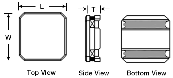 |
| L | 0.118
±0.004 | 3.00
±0.10 |
| W | 0.118
±0.004 | 3.00
±0.10 |
T
max | 0.047 | 1.20 |
| Part | Material | |
| 1 | Ferrite Core | Ni-Zn Ferrite |
| 2 | Copper Wire | Cu / P180 Grd 1 |
| 3 | Termination | Ag / Ni / Sn |
4 | Adhesive | Silicon Base Resin |
| Magnetic Powder | Ni-Zn Ferrite |
| Part Number | Inductance
@ 100KHz, 1V | Rated Current Based *1
on Inductance Change | Rated Current Based *2
on Temperature Rise | DC
Resistance | DC Resistance
Tolerance |
| LPC30121R0NE | 1.0 μH, ±30% | 1.90 A | 1.71 A | 45 mΩ | ±20% |
| LPC30121R5NE | 1.5 μH, ±30% | 1.50 A | 1.60 A | 55 mΩ | ±20% |
| LPC30122R2ME | 2.2 μH, ±30% | 1.25 A | 1.37 A | 60 mΩ | ±20% |
| LPC30122R7ME | 2.7 μH, ±20% | 1.20 A | 1.21 A | 90 mΩ | ±20% |
| LPC30123R3ME | 3.3 μH, ±20% | 1.05 A | 1.06 A | 90 mΩ | ±20% |
| LPC30124R7ME | 4.7 μH, ±20% | 0.90 A | 0.89 A | 150 mΩ | ±20% |
| LPC30126R8ME | 6.8 μH, ±20% | 0.70 A | 0.89 A | 190 mΩ | ±20% |
| LPC3012100ME | 10.0 μH, ±20% | 0.60 A | 0.72 A | 270 mΩ | ±20% |
| LPC3012150ME | 15.0 μH, ±20% | 0.50 A | 0.57 A | 450 mΩ | ±20% |
| LPC3012220ME | 22.0 μH, ±20% | 0.40 A | 0.50 A | 550 mΩ | ±20% |
| LPC3012330ME | 33.0 μH, ±20% | 0.30 A | 0.41 A | 900 mΩ | ±20% |
| LPC3012470ME | 47.0 μH, ±20% | 0.23 A | 0.35 A | 1250 mΩ | ±20% |
*1. Idc1: Based on inductance change (△L/Lo: -30%
*2. Idc2: Based on temperature rise (�T: 40ºC TYP.)
3015
| Units | Inches | mm |
Not marked |
| L | 0.118
±0.004 | 3.00
±0.10 |
| W | 0.118
±0.004 | 3.00
±0.10 |
T
max | 0.059 | 1.50 |
| Part | Material | |
| 1 | Ferrite Core | Ni-Zn Ferrite |
| 2 | Copper Wire | Cu / P180 Grd 1 |
| 3 | Termination | Ag / Ni / Sn |
4 | Adhesive | Silicon Base Resin |
| Magnetic Powder | Ni-Zn Ferrite |
| Part Number | Inductance
@ 100KHz, 1V | Rated Current Based *1
on Inductance Change | Rated Current Based *2
on Temperature Rise | DC
Resistance | DC Resistance
Tolerance |
| LPC30151R0NE | 1.0 μH, ±30% | 2.30 A | 2.30 A | 45 mΩ | ±20% |
| LPC30151R5NE | 1.5 μH, ±30% | 2.10 A | 2.10 A | 55 mΩ | ±30% |
| LPC30152R2ME | 2.2 μH, ±20% | 1.62 A | 2.00 A | 60 mΩ | ±20% |
| LPC30152R7ME | 2.7 μH, ±20% | 1.50 A | 1.95 A | 90 mΩ | ±20% |
| LPC30153R3ME | 3.3 μH, ±20% | 1.35 A | 1.80 A | 90 mΩ | ±20% |
| LPC30154R7ME | 4.7 μH, ±20% | 1.20 A | 1.60 A | 150 mΩ | ±20% |
| LPC30155R6ME | 5.6 μH, ±20% | 1.00 A | 1.40 A | 190 mΩ | ±20% |
| LPC30156R8ME | 6.8 μH, ±20% | 0.97 A | 1.30 A | 150 mΩ | ±20% |
| LPC3015100ME | 10.0 μH, ±20% | 0.80 A | 1.10 A | 220 mΩ | ±20% |
| LPC3015150ME | 15.0 μH, ±20% | 0.65 A | 1.00 A | 300 mΩ | ±20% |
| LPC3015180ME | 18.0 μH, ±20% | 0.57 A | 0.90 A | 410 mΩ | ±20% |
| LPC3015220ME | 22.0 μH, ±20% | 0.55 A | 0.80 A | 475 mΩ | ±20% |
| LPC3015330ME | 33.0 μH, ±20% | 0.45 A | 0.70 A | 650 mΩ | ±20% |
| LPC3015390ME | 39.0 μH, ±20% | 0.40 A | 0.50 A | 850 mΩ | ±20% |
| LPC3015470ME | 47.0 μH, ±20% | 0.35 A | 0.45 A | 1100 mΩ | ±20% |
| LPC3015680ME | 68.0 μH, ±20% | 0.30 A | 0.35 A | 1700 mΩ | ±20% |
| LPC3015820ME | 82.0 μH, ±20% | 0.27 A | 0.32 A | 1900 mΩ | ±20% |
| LPC3015101ME | 100.0 μH, ±20% | 0.25 A | 0.30 A | 2100 mΩ | ±20% |
*1. Idc1: Based on inductance change (△L/Lo: -30%
*2. Idc2: Based on temperature rise (△T: 40ºC TYP.)
4018
| Units | Inches | mm |
Marked 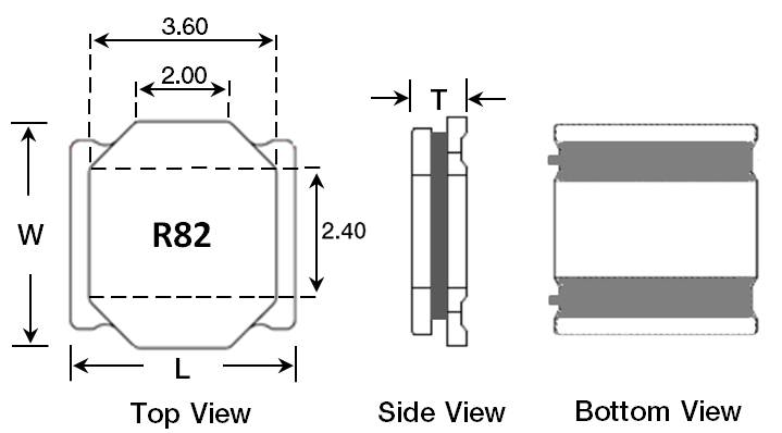 |
| L | 0.157
±0.008 | 4.00
±0.20 |
| W | 0.157
±0.008 | 4.00
±0.20 |
T
max |
(R82-2R7) |
0.074 | 1.88 |
| (3R3-221) |
0.071 |
1.80 |
| Part | Material | |
| 1 | Ferrite Core | Ni-Zn Ferrite |
| 2 | Copper Wire | Cu / P180 Grd 1 |
| 3 | Termination | Ag / Ni / Sn |
4 | Adhesive | Silicon Base Resin |
| Magnetic Powder | Ni-Zn Ferrite |
| Part Number | Inductance
@ 100KHz, 1V | Rated Current Based *1
on Inductance Change | Rated Current Based *2
on Temperature Rise | DC
Resistance | DC Resistance
Tolerance | Marking |
| LPC4018R82NE | 0.82 μH, ±30% | 4.20 A | 4.00 A | 16 mΩ | ±30% | R82 |
| LPC40181R0NE | 1.0 μH, ±30% | 4.70 A | 3.70 A | 19 mΩ | ±30% | 1R0 |
| LPC40181R2NE | 1.2 μH, ±30% | 4.00 A | 3.50 A | 21 mΩ | ±30% | 1R2 |
| LPC40181R5NE | 1.5 μH, ±30% | 3.50 A | 3.10 A | 27 mΩ | ±30% | 1R5 |
| LPC40182R2ME | 2.2 μH, ±20% | 3.00 A | 2.90 A | 37 mΩ | ±20% | 2R2 |
| LPC40182R7ME | 2.7 μH, ±20% | 2.40 A | 2.30 A | 43 mΩ | ±20% | 2R7 |
| LPC40183R3ME | 3.3 μH, ±20% | 2.30 A | 2.20 A | 55 mΩ | ±20% | 3R3 |
| LPC40184R7ME | 4.7 μH, ±20% | 2.00 A | 1.90 A | 70 mΩ | ±20% | 4R7 |
| LPC40186R8ME | 6.8 μH, ±20% | 1.60 A | 1.50 A | 98 mΩ | ±20% | 6R8 |
| LPC4018100ME | 10.0 μH, ±20% | 1.40 A | 1.30 A | 150 mΩ | ±20% | 100 |
| LPC4018150ME | 15.0 μH, ±20% | 1.10 A | 1.00 A | 220 mΩ | ±20% | 150 |
| LPC4018220ME | 22.0 μH, ±20% | 0.95 A | 0.90 A | 290 mΩ | ±20% | 220 |
| LPC4018330ME | 33.0 μH, ±20% | 0.75 A | 0.70 A | 460 mΩ | ±20% | 330 |
| LPC4018470ME | 47.0 μH, ±20% | 0.62 A | 0.60 A | 650 mΩ | ±20% | 470 |
| LPC4018680ME | 68.0 μH, ±20% | 0.50 A | 0.50 A | 940 mΩ | ±20% | 680 |
| LPC4018101ME | 100.0 μH, ±20% | 0.45 A | 0.42 A | 1300 mΩ | ±20% | 101 |
| LPC4018151ME | 150.0 μH, ±20% | 0.35 A | 0.32 A | 2000 mΩ | ±20% | 151 |
| LPC4018221ME | 220.0 μH, ±20% | 0.30 A | 0.28 A | 2960 mΩ | ±20% | 221 |
*1. Idc1: Based on inductance change (△L/Lo: -30%
*2. Idc2: Based on temperature rise (△T: 40ºC TYP.)
4025
| Units | Inches | mm |
Marked 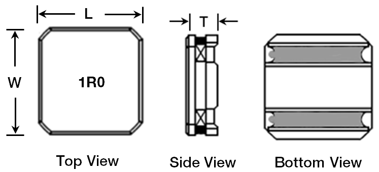 |
| L | 0.157±0.008 | 4.00±0.20 |
| W | 0.157±0.008 | 4.00±0.20 |
T
max |
0.098 |
2.50 |
| Part | Material | |
| 1 | Ferrite Core | Ni-Zn Ferrite |
| 2 | Copper Wire | Cu / P180 Grd 1 |
| 3 | Termination | Ag / Ni / Sn |
4 | Adhesive | Silicon Base Resin |
| Magnetic Powder | Ni-Zn Ferrite |
| Part Number | Inductance
@ 100KHz, 1V | Rated Current Based *1
on Inductance Change | Rated Current Based *2
on Temperature Rise | DC
Resistance | DC Resistance
Tolerance | Marking |
| LPC40251R0NE |
1.0 μH, ±30% |
3.00 A |
3.00 A |
12 mΩ | ±30% |
1R0 |
| LPC40251R2NE |
1.2 μH, ±30% |
2.75 A |
2.75 A |
18 mΩ | ±30% |
1R2 |
| LPC40252R2NE |
2.2 μH, ±30% |
2.10 A |
2.10 A |
22 mΩ | ±30% |
2R2 |
| LPC40253R3ME |
3.3 μH, ±20% |
1.60 A |
1.60 A |
30 mΩ |
±20% |
3R3 |
| LPC40254R7ME |
4.7 μH, ±20% |
1.40 A |
1.40 A |
40 mΩ | ±20% |
4R7 |
| LPC40256R8ME |
6.8 μH, ±20% |
1.20 A |
1.20 A |
70 mΩ | ±20% |
6R8 |
| LPC4025100ME |
10.0 μH, ±20% |
0.97 A |
0.97 A |
85 mΩ | ±20% |
100 |
| LPC4025150ME |
15.0 μH, ±20% |
0.77 A |
0.77 A |
120 mΩ | ±20% |
150 |
| LPC4025220ME |
22.0 μH, ±20% |
0.67 A |
0.67 A |
195 mΩ | ±20% |
220 |
| LPC4025330ME |
33.0 μH, ±20% |
0.50 A |
0.50 A |
305 mΩ | ±20% |
330 |
| LPC4025470ME |
47.0 μH, ±20% |
0.40 A |
0.40 A |
495 mΩ | ±20% |
470 |
| LPC4025680ME |
68.0 μH, ±20% |
0.35 A |
0.35 A |
710 mΩ | ±20% |
680 |
| LPC4025101ME |
100.0 μH, ±20% |
0.30 A |
0.30 A |
1000 mΩ | ±20% |
101 |
| LPC4025151ME |
150.0 μH, ±20% |
0.22 A |
0.22 A |
1600 mΩ | ±20% |
151 |
| LPC4025221ME |
220.0 μH, ±20% |
0.20 A |
0.20 A |
2300 mΩ | ±20% |
121 |
*1. Idc1: Based on inductance change (△L/Lo: -30%
*2. Idc2: Based on temperature rise (△T: 40ºC TYP.)
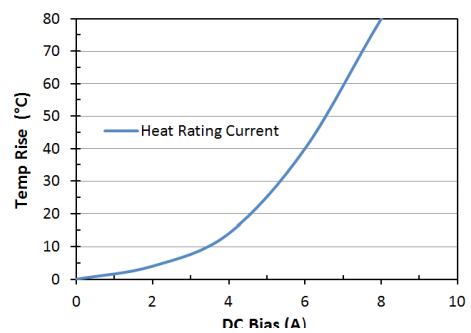
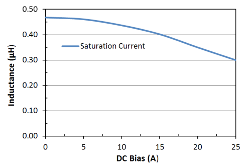
5040
| Units | Inches | mm |
Marked 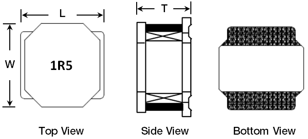 |
| L | 0.197±0.008 | 5.00±0.20 |
| W | 0.197±0.008 | 5.00±0.20 |
T
max |
0.157 |
4.00 |
| Part | Material | |
| 1 | Ferrite Core | Ni-Zn Ferrite |
| 2 | Copper Wire | Cu / P180 Grd 1 |
| 3 | Termination | Ag / Ni / Sn |
4 | Adhesive | Silicon Base Resin |
| Magnetic Powder | Ni-Zn Ferrite |
| Part Number | Inductance
@ 100KHz, 1V | Rated Current Based *1
on Inductance Change | Rated Current Based *2
on Temperature Rise | DC
Resistance | DC Resistance
Tolerance | Marking |
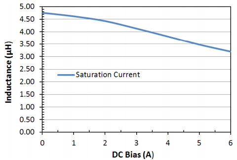
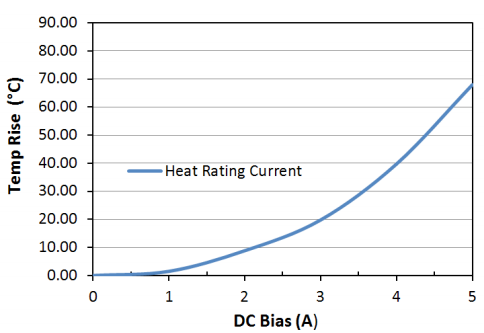
| LPC50401R5NE | 1.5 μH, ±30% | 6.00 A | 3.60 A | 15 mΩ | ±20% | 1R5 |
| LPC50402R2NE | 2.2 μH, ±30% | 4.60 A | 3.50 A | 17 mΩ | ±20% | 2R2 |
| LPC50403R3ME | 3.3 μH, ±20% | 3.80 A | 3.30 A | 22 mΩ | ±20% | 3R3 |
| LPC50404R7ME | 4.7 μH, ±20% | 3.30 A | 3.10 A | 29 mΩ | ±20% | 4R7 |
| LPC50406R8ME | 6.8 μH, ±20% | 2.60 A | 2.30 A | 49 mΩ | ±20% | 6R6 |
| LPC50408R2ME | 8.2 μH, ±20% | 2.40 A | 2.20 A | 54 mΩ | ±20% | 8R2 |
| LPC5040100ME | 10.0 μH, ±20% | 2.30 A | 2.10 A | 56 mΩ | ±20% | 100 |
| LPC5040150ME | 15.0 μH, ±20% | 2.00 A | 1.80 A | 80 mΩ | ±20% | 150 |
| LPC5040220ME | 22.0 μH, ±20% | 1.60 A | 1.40 A | 126 mΩ | ±20% | 220 |
| LPC5040270ME | 27.0 μH, ±20% | 1.40 A | 1.30 A | 165 mΩ | ±20% | 270 |
| LPC5040330ME | 33.0 μH, ±20% | 1.30 A | 1.20 A | 180 mΩ | ±20% | 330 |
| LPC5040470ME | 47.0 μH, ±20% | 1.10 A | 0.90 A | 270 mΩ | ±20% | 470 |
*1. Idc1: Based on inductance change (△L/Lo: -30%
*2. Idc2: Based on temperature rise (△T: 40ºC TYP.)
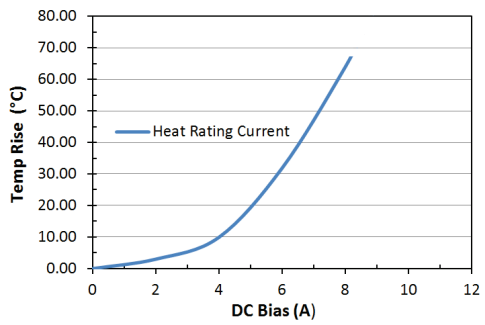
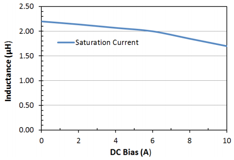
6045
| Units | Inches | mm |
Marked 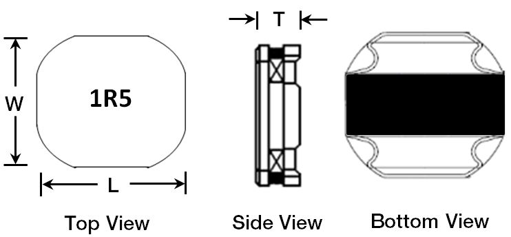 |
| L | 0.236±0.008 | 6.00±0.20 |
| W | 0.236±0.008 | 6.00±0.20 |
T
max |
0.177 |
4.50 |
| Part | Material | |
| 1 | Ferrite Core | Ni-Zn Ferrite |
| 2 | Copper Wire | Cu / P180 Grd 1 |
| 3 | Termination | Ag / Ni / Sn |
4 | Adhesive | Silicon Base Resin |
| Magnetic Powder | Ni-Zn Ferrite |
| Part Number | Inductance
@ 100KHz, 1V | Rated Current Based *1
on Inductance Change | Rated Current Based *2
on Temperature Rise | DC
Resistance | DC Resistance
Tolerance | Marking |
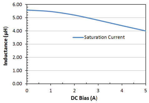
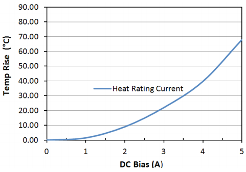
| LPC60451R0NE | 1.0 μH, ±30% | 8.60 A | 6.50 A | 10 mΩ | ±30% | 1R0 |
| LPC60451R3NE | 1.3 μH, ±30% | 8.00 A | 6.00 A | 11 mΩ | ±30% | 1R3 |
| LPC60451R8NE | 1.8 μH, ±20% | 7.00 A | 5.30 A | 12 mΩ | ±30% | 1R8 |
| LPC60452R2NE | 2.2 μH, ±20% | 6.10 A | 5.00 A | 13 mΩ | ±30% | 2R2 |
| LPC60453R0NE | 3.0 μH, ±20% | 5.00 A | 4.80 A | 17 mΩ | ±30% | 3R0 |
| LPC60453R3NE | 3.3 μH, ±20% | 4.50 A | 4.50 A | 17 mΩ | ±30% | 3R3 |
| LPC60454R5NE | 4.5 μH, ±20% | 4.30 A | 3.80 A | 23 mΩ | ±30% | 4R5 |
| LPC60454R7NE | 4.7 μH, ±20% | 4.00 A | 3.70 A | 23 mΩ | ±30% | 4R7 |
| LPC60455R6NE | 5.6 μH, ±20% | 3.80 A | 3.60 A | 26 mΩ | ±30% | 5R6 |
| LPC60456R3NE | 6.3 μH, ±20% | 3.80 A | 3.60 A | 26 mΩ | ±30% | 6R3 |
| LPC60456R8NE | 6.8 μH, ±20% | 3.60 A | 3.50 A | 34 mΩ | ±30% | 6R8 |
| LPC60458R2NE | 8.2 μH, ±20% | 3.20 A | 3.10 A | 41 mΩ | ±30% | 8R2 |
| LPC6045100ME | 10.0 μH, ±20% | 3.10 A | 3.00 A | 45 mΩ | ±20% | 100 |
| LPC6045150ME | 15.0 μH, ±20% | 2.30 A | 2.30 A | 80 mΩ | ±20% | 150 |
| LPC6045220ME | 22.0 μH, ±20% | 1.90 A | 1.90 A | 112 mΩ | ±20% | 220 |
| LPC6045330ME | 33.0 μH, ±20% | 1.50 A | 1.50 A | 170 mΩ | ±20% | 330 |
| LPC6045470ME | 47.0 μH, ±20% | 1.30 A | 1.30 A | 210 mΩ | ±20% | 470 |
| LPC6045560ME | 56.0 μH, ±20% | 1.20 A | 1.20 A | 270 mΩ | ±20% | 560 |
| LPC6045680ME | 68.0 μH, ±20% | 1.00 A | 1.00 A | 325 mΩ | ±20% | 680 |
| LPC6045101ME | 100.0 μH, ±20% | 0.90 A | 0.90 A | 460 mΩ | ±20% | 101 |
| LPC6045221ME | 220.0 μH, ±20% | 0.55 A | 0.50 A | 920 mΩ | ±20% | 221 |
*1. Idc1: Based on inductance change (△L/Lo: -30%
*2. Idc2: Based on temperature rise (△T: 40ºC TYP.)
Environmental
| SPECIFICATION | TEST PARAMETERS |
| VIBRATION | ΔL/Lo : ≤ ±10% There shall be no mechanical damage | Solder specimen inductor on the test printed circuit board. Apply vibrations in each of the x, y and z directions for 2 house for a total of 6 hours. Frequency : 10 to 50 Hz Amplitude : 1.5mm |
| SOLDERABILITY | The metalized area must have 90% minimum solder coverage. | Dip pads in flux and dip in solder pot (NP303) at 240ºC ±5ºC |
| HIGH TEMPERATURE RESISTANCE | ΔL/Lo : ≤ ±10% There shall be no mechanical damage or electrical damage. | The sample shall be left for 96 hours in an atmosphere with a temperature of 85±2ºC and a normal humidity. Upon completion of the test, the measurement shall be made after the sample has been left in a normal temperature and normal humidity for 1 hour. |
| LOW TEMPERATURE | ΔL/Lo : ≤ ±10% There shall be no mechanical damage or electrical damage. | The sample shall be left for 96 hours in an atmosphere with a temperature of –30±2ºC. Upon completion of the test, the measurement shall be made after the sample has been left in a normal temperature and normal humidity for 1 hour. |
| MOISTURE STORAGE | ΔL/Lo : ≤ ±10% There shall be no mechanical damage | The sample shall be left for 96 hours in a temperature of 40±2ºC and a humidity(RH) of 90~95%. Upon completion of the test, the measurement shall be made after the sample has been left in a normal temperature and normal humidity more than 1 hour. |
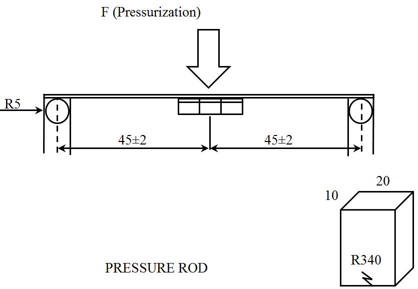
| SUBSTRATE BENDING | L/Lo : ≤ ±10% There shall be no mechanical damage or electrical damage | The sample shall be soldered onto the printed circuit board and a load applied until the figure in the arrow direction is made approximately 3mm (keep time 5 ±1 seconds).
 |
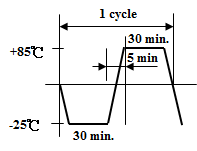
| THERMAL SHOCK | ΔL/Lo : ≤ ±10% There shall be no damage or problems. | The sample shall be subject to 5 continous cycles, such as shown in the following temperature cycle. Measure the test items after leaving the inductors at room temperature and humidity for 1 hour.
 |
| COMPONENT ADHESION (PUSH TEST) | 10N Min (LPC 2410, 3010)
12N Min (LPC 3012, 3015,
4018, 4025, 5040, 6045) | The device should be reflow soldered (245 ±5ºC for 10 seconds) to a copper substrate a dynamometer force gauge should be applied to the side of the component the device must withstand a minimum force of 10N or 12N without failure of the termination attached to the component. |
Soldering
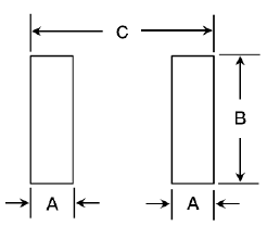
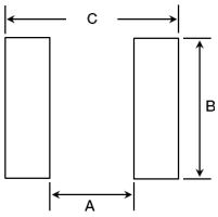
RECOMMENDED FOOTPRINT:
| Size Codes | Units | 2410 | 3010 | 3012 | 3015 | 4018 | 4025 | 5040 | 6045 |
| A | In | 0.031 | 0.031 | 0.031 | 0.031 | 0.059 | 0.059 | 0.059 | 0.063 |
| mm | 0.800 | 0.800 | 0.800 | 0.800 | 1.500 | 1.500 | 1.500 | 1.600 |
| B | In | 0.079 | 0.079 | 0.106 | 0.106 | 0.142 | 0.142 | 0.157 | 0.244 |
| mm | 2.000 | 2.000 | 2.700 | 2.700 | 3.600 | 3.600 | 4.000 | 5.700 |
| C | In | 0.098 | 0.098 | 0.087 | 0.087 | 0.179 | 0.179 | 0.201 | 0.248 |
| mm | 2.500 | 2.500 | 2.200 | 2.200 | 4.550 | 4.550 | 5.100 | 6.300 |
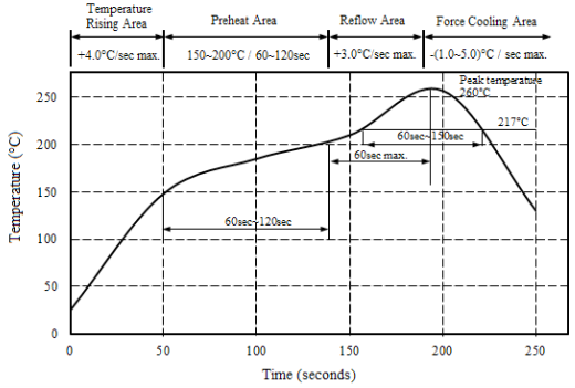
RECOMMENDED SOLDER ATTACHMENT: REFLOW SOLDERING:
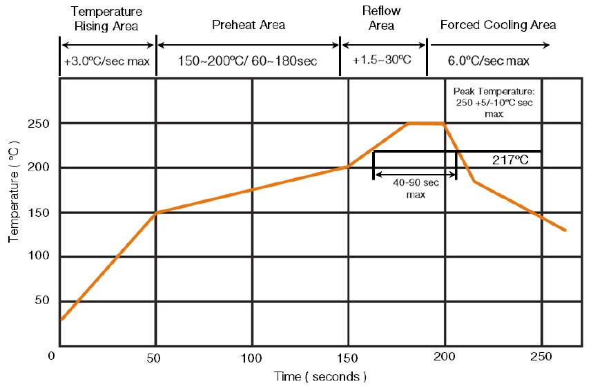
Reflow: 2 times max
Peak Temperature: 255ºC
Max Time Above 217ºC: 90 sec max
If hand soldering must be used, follow these precautions:
Use solder iron of less than 30W when soldering.
Do not allow soldering iron tip to directly touch the ferrite body outside of the terminal electrode.
2 seconds maximum at 280ºC.
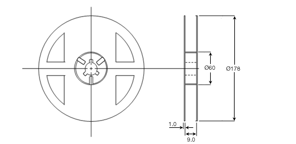
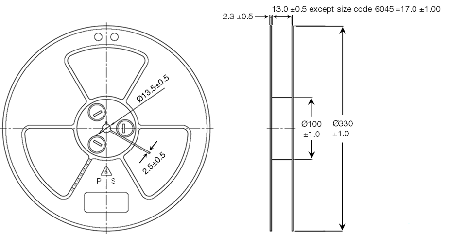
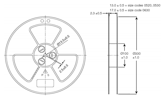
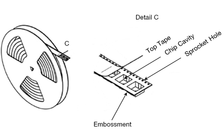
REEL DIMENSIONS (Unit: mm)
| 7” DIA. REEL SIZE |
| SIZE CODE | REEL QTY | TAPE TYPE | TAPE CODE |
| 2410 | 2000 | Embossed | E |
| 3010 | 2000 | Embossed | E |
| 3012 | 2000 | Embossed | E |
| 3015 | 2000 | Embossed | E |
| 13” DIA. REEL SIZE |
| SIZE CODE | REEL QTY | TAPE TYPE | TAPE CODE |
| 4018 | 3000 | Embossed | E |
| 4025 | 3000 | Embossed | E |
| 5040 | 1000 | Embossed | E |
| 6045 | 1000 | Embossed | E |
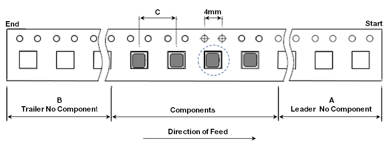
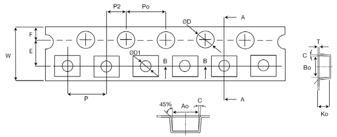
TAPPING FIGURE
TAPE DIMENSIONS (Unit: mm)
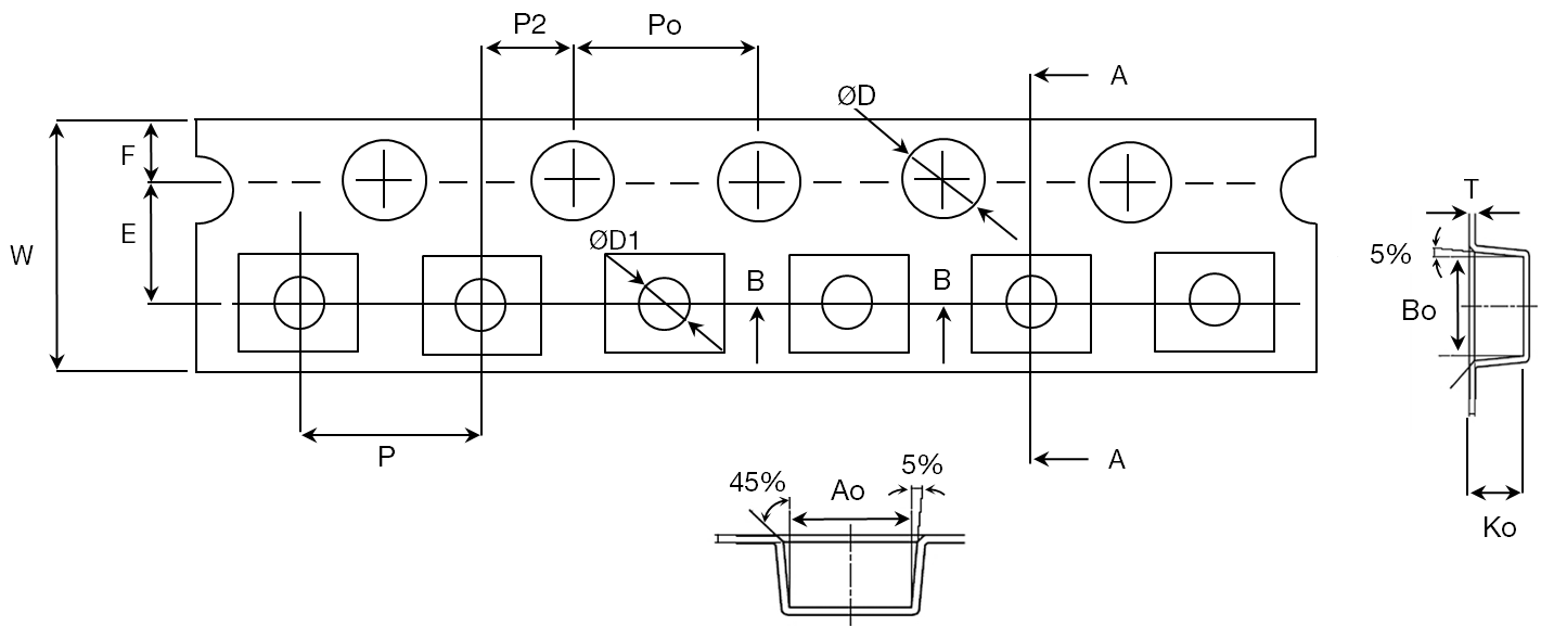
| Size Codes | A0 | B0 | K0 | T | W | E | F | D | D1 | P | P2 | Po | 10Po |
| 2410 | 2.75 | 2.75 | 1.30 | 0.23 | 8.00 | 1.75 | 3.50 | 1.50 | 1.00 | 4.00 | 2.00 | 4.00 | 40.00 |
| 3010 | 3.30 | 3.30 | 1.40 | 0.23 | 8.00 | 1.75 | 3.50 | 1.50 | 1.00 | 4.00 | 2.00 | 4.00 | 40.00 |
| 3012 | 3.30 | 3.30 | 1.40 | 0.23 | 8.00 | 1.75 | 3.50 | 1.50 | 1.00 | 4.00 | 2.00 | 4.00 | 40.00 |
| 3015 | 3.30 | 3.30 | 1.70 | 0.23 | 8.00 | 1.75 | 3.50 | 1.50 | 1.00 | 4.00 | 2.00 | 4.00 | 40.00 |
| 4018 | 4.50 | 4.35 | 1.90 | 0.25 | 12.00 | 1.75 | 5.50 | 1.50 | 1.50 | 8.00 | 2.00 | 4.00 | 40.00 |
| 4025 | 4.20 | 4.20 | 2.75 | 0.30 | 12.00 | 1.75 | 5.50 | 1.50 | 1.50 | 8.00 | 2.00 | 4.00 | 40.00 |
| 5040 | 5.35 | 5.80 | 4.70 | 0.40 | 16.00 | 1.75 | 5.50 | 1.50 | 1.50 | 8.00 | 2.00 | 4.00 | 40.00 |
| 6045 | 6.30 | 6.30 | 4.70 | 0.40 | 16.00 | 1.75 | 7.50 | 1.50 | 1.50 | 12.00 | 2.00 | 4.00 | 40.00 |
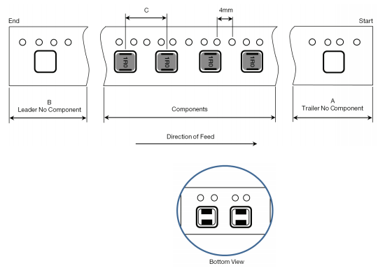
PACKAGING FORM (Unit: mm)
| Size Codes | A | B | C |
| 2410 | 160 | 80 | 4 |
| 3010 | 160 | 80 | 8 |
| 3012 | 160 | 80 | 8 |
| 3015 | 160 | 80 | 8 |
| 4018 | 400 | 200 | 8 |
| 4025 | 400 | 200 | 8 |
| 5040 | 400 | 200 | 8 |
| 6045 | 400 | 200 | 12 |
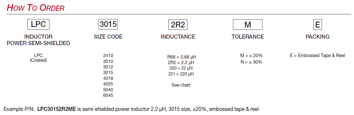
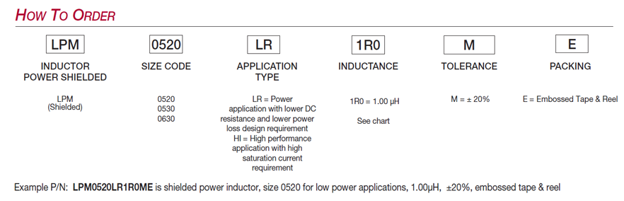
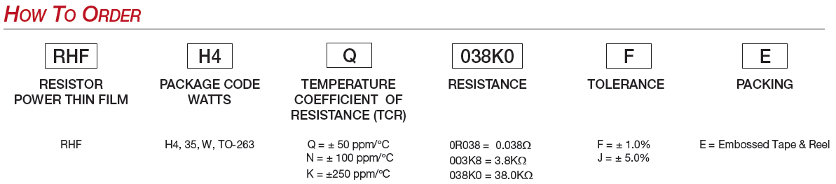
How to Order