Resistor Wirewound Chassis Mount
RWC Series
This specific product line is not for new designs.
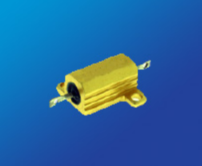
Chassis mount resistors are manufactured using wirewound resistor technology in a large ceramic core molded into an extruded aluminum, chassis-mount housing. The wirewound design maximizes pulse handling, while the aluminum housing provides superior heat conduction.
For applications where the design of the resistor is to promote heat loss and cooling, a chassis mount resistor is an ideal resistor for your next design. Our chassis mount pulse-withstanding resistors are preferred by design engineers for their low temperature coefficient of resistance (TCR).
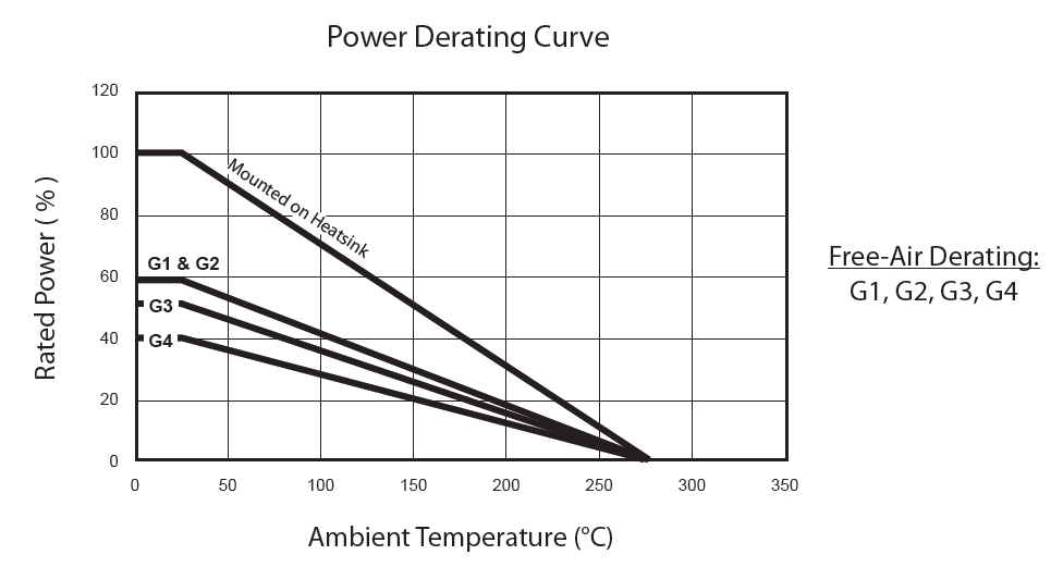
Chassis mount low TCR resistors that can be attached to heat sinks to dissipate heat, increase the capability of the resistor. Panel mount resistors are ideal for shunt and current monitoring circuits.
Johanson Dielectrics RWC chassis mount resistors are available with non-inductive windings. Four terminal designs are available as well for improved thermal management. Resistance values range from 0.005 ohm up to 250k ohm.
Contact us for your unique resistor requirement. Whether it’s the temperature of coefficient, tolerance or form factor you’re looking for, our applications engineers will assist in fast tracking your design to production.
For applications where the design of the resistor is to promote heat loss and cooling, a chassis mount resistor is an ideal resistor for your next design. Our chassis mount pulse-withstanding resistors are preferred by design engineers for their low temperature coefficient of resistance (TCR).
Chassis mount low TCR resistors that can be attached to heat sinks to dissipate heat, increase the capability of the resistor. Panel mount resistors are ideal for shunt and current monitoring circuits.
Johanson Dielectrics RWC chassis mount resistors are available with non-inductive windings. Four terminal designs are available as well for improved thermal management. Resistance values range from 0.005 ohm up to 250k ohm.
Contact us for your unique resistor requirement. Whether it’s the temperature of coefficient, tolerance or form factor you’re looking for, our applications engineers will assist in fast tracking your design to production.
KEY FEATURES:
- Resistances from 0.005 to 250kOhms
- Tolerance to ± 0.01%
- High Temperature: - 55ºC to + 275ºC
- Low TCR: ± 20ppm/ºC
- Power Rating 5 to 50 Watts
- Excellent Pulse Handling
- Non-Inductive windings available
- Four Terminal Versions Available (Call Factory)
- RoHS Compliant
APPLICATIONS:
- Motor Control
- Braking Systems
- Welding
- X-Ray
| PRODUCT SERIES (RWC) | RESISTANCE RANGE (Ω) 1 | POWER RATING (W @ 25ºC) | DIELECTRIC STRENGTH | TEMPERATURE COEFFICIENT | TEMPERATURE RANGE | ||
|---|---|---|---|---|---|---|---|
| FREE AIR |
COMMERCIAL | MIL | |||||
| G1 | 0.01 to 22K | 4.5 | 7.5 a | 5 a | 1500 VAC |
|
-55°C to + 250°C |
| G2 | 0.01 to 47K | 7.5 | 12.5 a | 10 a | 1500 VAC | ||
| G3 | 0.01 to 90K | 12 | 25 b | 20 b | 2500 VAC | ||
| G4 | 0.01 to 250K | 20 | 50 c | 30 c | 3500 VAC | ||
TOLERANCE: ± 0.01 to ± 10% (1% Standard)
1 For non-inductive windings, divide maximum resistance by 2
a Heatsink required: 0.040 [1.0] Aluminum Plate, 129 in2 [832 cm2] or equiv.
b Heatsink required: 0.040 [1.0] Aluminum Plate, 167 in2 [1077 cm2] or equiv.
c Heatsink required: 0.059 [1.5] Aluminum Plate, 291 in2 [1877 cm2] or equiv.
d Heatsink required: 0.125 [3.2] Aluminum Plate, 294in2 [1896cm2] or equiv.
e Heatsink required: 0.125 [3.2] Aluminum Plate, 895 in2 [5780 cm2] or equiv.
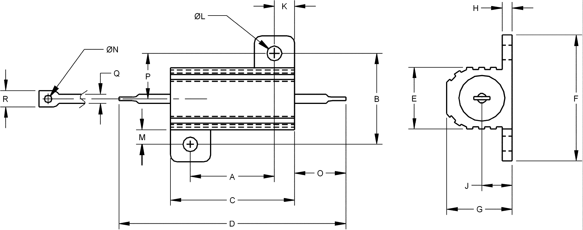
Mechanical Characteristics
| Package Code | G1 | G2 | G3 | G4 | |
|---|---|---|---|---|---|
Dimensions Inches [mm] |
A (Tolerances) ±0.005 [±0.13 mm] |
0.444 [11.28] | 0.562 [14.27] | 0.719 [18.26] | 1.563 [39.70] |
| B (Tolerances) ±0.005 [±0.13 mm] |
0.490 [12.45] | 0.625 [15.88] | 0.781 [19.84] | 0.844 [21.44] | |
| C (Tolerances) ±0.031 [±0.79 mm] |
0.600 [15.24] | 0.750 [19.05] | 1.062 [26.97] | 1.968 [49.99] | |
| D (Tolerances) ±0.062 [±1.57 mm] |
1.125 [28.58] | 1.320 [33.53] | 1.870 [47.50] | 2.760 [70.10] | |
| E (Tolerances) ±0.015 [±0.38 mm] |
0.334 [8.48] | 0.430 [10.92] | 0.530 [13.46] | 0.615 [15.62] | |
| F (Tolerances) ±0.015 [±0.38 mm] |
0.646 [16.41] | 0.800 [20.32] | 1.080 [27.43] | 1.140 [28.96] | |
| G (Tolerances) ±0.015 [±0.38 mm] |
0.320 [8.13] | 0.400 [10.16] | 0.560 [14.22] | 0.615 [15.62] | |
| H (Tolerances) ±0.010 [±0.25 mm] |
0.065 [1.65] | 0.075 [1.91] | 0.085 [2.16] | 0.085 [2.16] | |
| J (Tolerances) ±0.010 [±0.25 mm] |
0.140 [3.56] | 0.190 [4.83] | 0.260 [6.60] | 0.300 [7.62] | |
| K (Tolerances) ±0.010 [±0.25 mm] |
0.078 [1.98] | 0.093 [2.36] | 0.172 [4.37] | 0.196 [4.98] | |
| L (Tolerances) ±0.005 [±0.13 mm] |
0.093 [2.36] | 0.093 [2.36] | 0.125 [3.18] | 0.125 [3.18] | |
| M (Tolerances) ±0.015 [±0.38 mm] |
0.078 [1.98] | 0.102 [2.60] | 0.125 [3.18] | 0.125 [3.18] | |
| N (Tolerances) ±0.006 [±0.15 mm] |
0.050 [1.27] | 0.080 [2.03] | 0.080 [2.03] | 0.080 [2.03] | |
| O (Tolerances) ±0.062 [±1.57 mm] |
0.266 [6.76] | 0.312 [7.93] | 0.438 [11.13] | 0.438 [11.13] | |
| P (Tolerances) ±0.031 [±0.79 mm] |
0.245 [6.22] | 0.312 [7.92] | 0.391 [9.93] | 0.422 [10.72] | |
| Q (Tolerances) ±0.002 [±0.05 mm] |
0.051 [1.30] | 0.098 [2.49] | 0.098 [2.49] | 0.098 [2.49] | |
| R (Tolerances) ±0.031 [±0.79 mm] |
0.085 [2.16] | 0.160 [4.06] | 0.185 [4.70] | 0.185 [4.70] | |
| MIL-R-39009 / MIL-R-18546 | RER-60 / RE-60 | RER-65 / RE-65 | RER-70 / RE-70 | RER-75 / RE-75 | |
Environmental Performance
| Environmental Performance (MIL-STD 202) |
 R R |
|---|---|
| Vibration | ±0.1 % + 0.05 Ω |
| Load Life | ± 1% + 0.05 Ω |
| Moisture Resistance | ±0.2 % + 0.05 Ω |
| Dielectric | ±0.2 % + 0.05 Ω |
| Storage | ±0.2 % + 0.05 Ω |
| Shock | ±0.1 % + 0.05 Ω |
| Thermal Shock | ±0.2 % + 0.05 Ω |
| 5X Overload (5s) | ±0.2 % + 0.05 Ω |
CONSTRUCTION NOTES:
- Centerless ground ceramic core
- Tinned copper or copperweld leads
- All welded terminations
- High Temperature epoxy molding compound
- Anodized aluminum housing
* Moisture Sensitivity Level: MSL-1
Available Options (Consult Factory)
- Special Testing Requirements
- Special Pulse Requirements
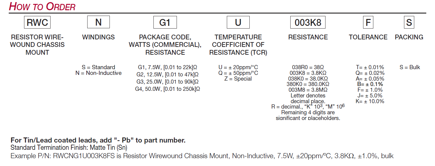
How to Order