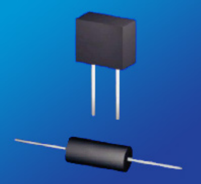
A precision wirewound resistor is designed to absorb high energy impulses. Stable materials used in the wiring of a wirewound resistor leads to high accuracy, superior stability, and low temperature coefficient of resistance (TCR).
KEY FEATURES:
Low TCR ±2ppm/°C
Temperature Coefficients of ± 2ppm/°C
Temperature Range -55°C to +145°C
Resistance to 6 Mega-Ohms
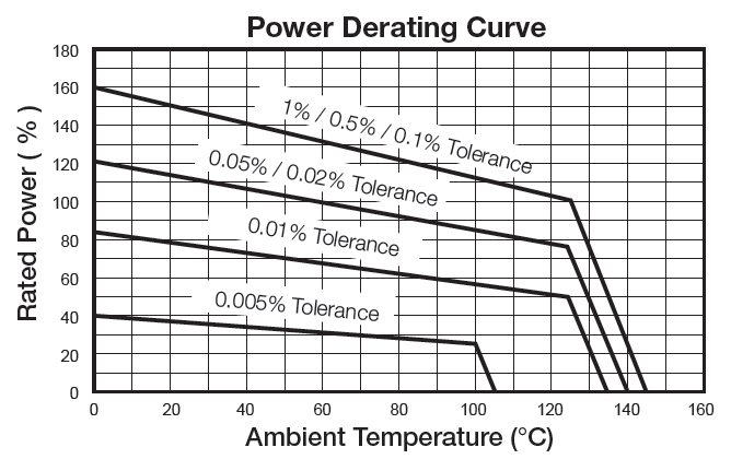
Resistance Tolerance starting at ± 0.005%
Long Term Stability / 100ppm/year
High TCR Available - Platinum & Balco Wire
Matched Resistance Sets to ± 0.001 and ± 0.5 ppm/°C
100% Acceptance Tested
RoHS Compliant
Options available: Wide TCR Range, High Stability and Fast Rise Time
APPLICATIONS:
Smart Grid Metering
Power Inverters
Engine Sensors
Temperature Sensors
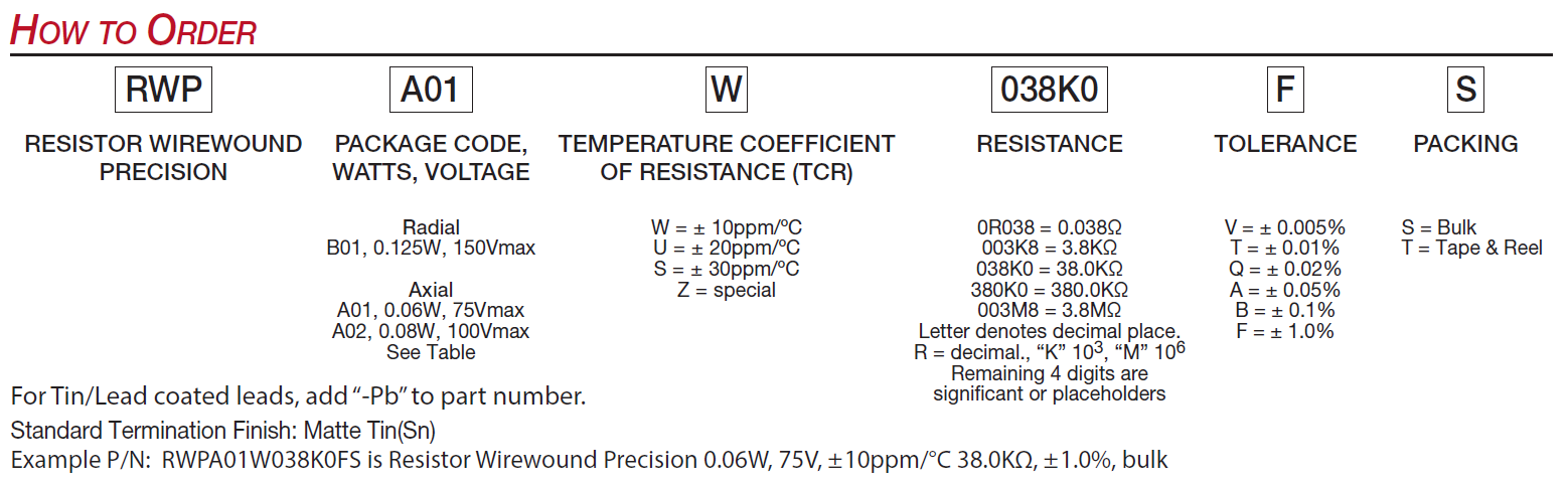
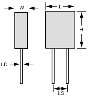
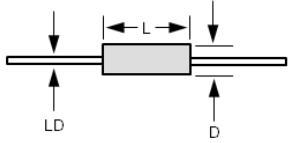
Johanson Dielectrics precision wirewound resistors (RWP series) are designed to meet the demanding requirements for high energy impulses. Our wirewound resistors achieve tight tolerances starting at ±0.005%, and are available as radial and axial resistors for thru-hole mounting or soldering of wires on the leads. We design your radial and axial resistors to address the majority of industry standard impulse requirements through mass and wire geometry (length and diameter) design. Contact us for your unique impulse requirements. Our applications engineers will assist in finding the right wirewound resistor for your application.
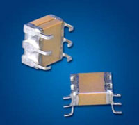
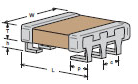
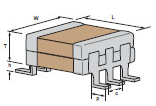
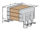
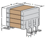
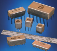
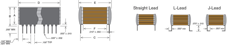
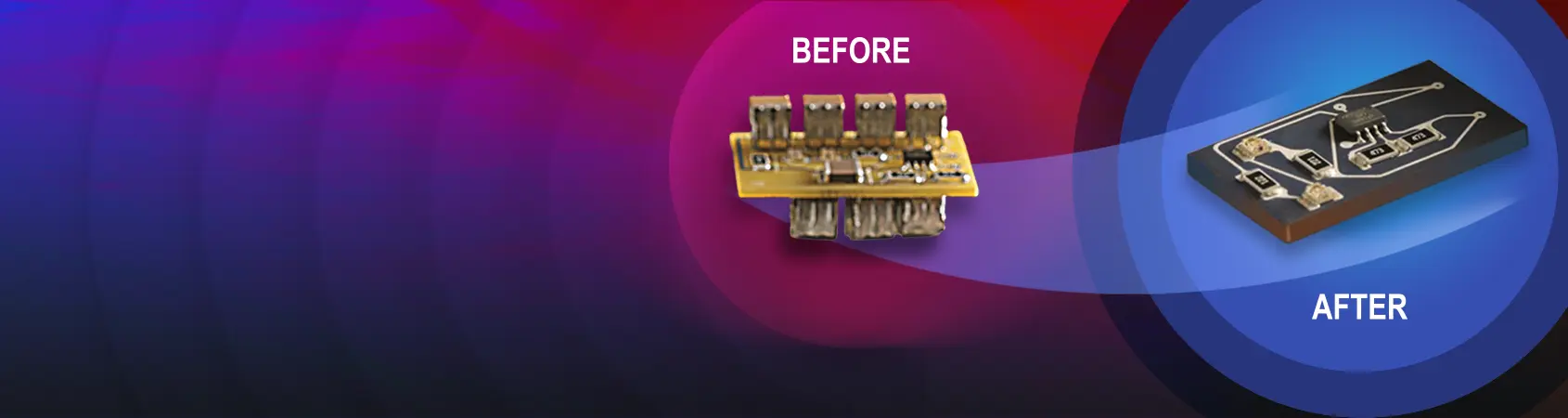
JDI's Mini-Switch Mode® ceramic capacitors combine the advantages of high capacitance found in tantalum capacitors with very low ESR performance of ceramic capacitors. The "J" and "L" lead configurations replace 1825 and 2225 SMT chips to provide stress relief and prevent cracking due to thermal cycling or mechanical board flexing. Another plus of the J-lead style is that this configuration allows use of the same solder lands as the SMT chips. See the Switch-Mode section for larger values. See also the Technical Notes on soldering and handling and suggested solder lands.
Key Features:
Stress Relief from Cracking due to Thermal Cycling, TCE Mismatches or Board Flexing
25 to 500 VDC Ratings
Custom Sizes, Voltages, and Values Available
Ideal for DC-DC Power Supply Applications
General Specifications:
Stress Relief from Cracking due to Thermal Cycling, TCE Mismatches or Board Flexing
* Not all combinations create valid part numbers, ask our Apps Engineering Team for assistance creating a valid part number Request for assistance
Click below to see the new Global Part Number Reference Chart for this product
Subfamily
SMPS P-Series - PME
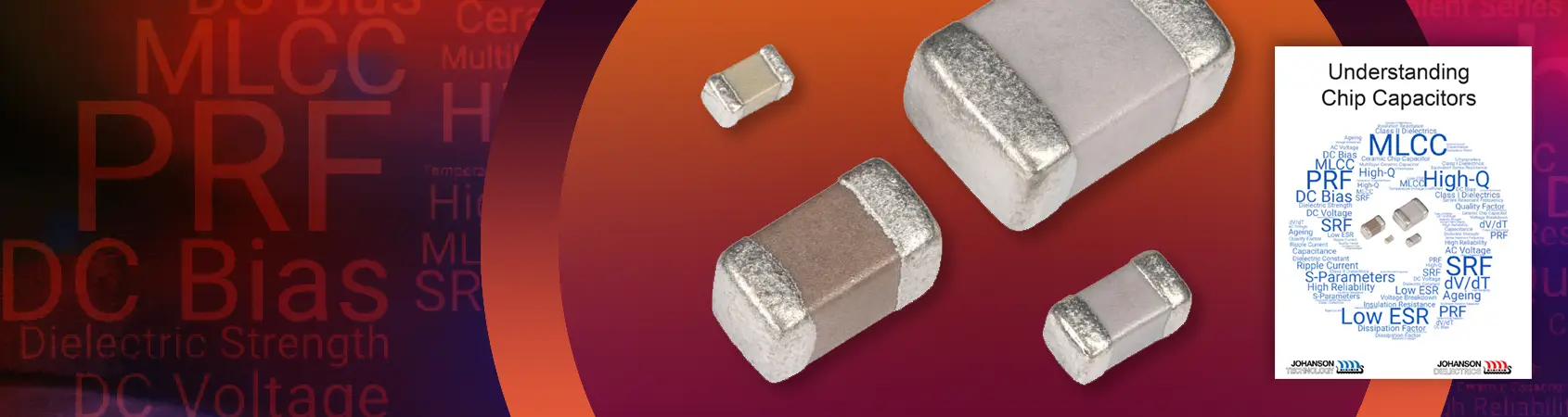
Size Multi-Layer Capacitor (MLCC)
0201
0402
0403
0504
0603
0805
1111
1206
1210
1808
1812
1825
2220
2525
2525
3838
Special
Voltage
Industry Std examples:
6.3V
200V
Special Code
3 numeric values in the voltage field - No "R" in the 3 digits - used for values greater than or equal to 10 Volts
1st two digits are Signiant; third digit denotes number of zeros,
100 = 10 Volts
101 = 100 Volts
402 = 4000 Volts
With "R" in the 3 digits - used for capacitance values less than 10 Volts
R = decimal point.
6R3 = 6.3 Volts
Dielectric Temp Char
Class 1 Temp Compensating
NP0/C0G
Class 2 Hi-Dielectric Constants
BX
X7R
X8R
Miscellaneous
Define in special code
Capacitance
Industry Std examples:
1 pF
15 pF
4,700 pF
+ Alpha Cap Codes
Special Code
3 numeric values in the voltage field - No "R" in the 3 digits - used for values greater than or equal to 10 pF
· 1st two digits are Signiant; third digit denotes number of zeros,
100 = 10 pF
101 = 100 pF
With "R" in the 3 digits - used for capacitance values less than 10pF
R = decimal point.
R75 = 0.75 pF
8R2 = 8.2 pF
Tolerance
NP0 <10pF
±0.05pF
±0.1pF
±0.25pF
±0.5pF
NP0 >10pF
±1%
±2%
±5%
±10%
±20%
X7R
±5%
±10%
±20%
Special Code
Marking
No Mark
EIA Mark
Cap Code & Tol
Special Code
Marking available on 0805 and larger sizes
Termination
Surface Mount
Ni/Sn (RoHS)
Ni/SnPb
Cu/Sn (RoHS)
Cu/SnPb
Polyterm Sn (RoHS)
Polyterm Sn/Pb
Surface Mount
Ni/Au (RoHS)
Pd Ag Strike (RoHS)
Pd/Ag (RoHS)
Pt/Ag (RoHS)
Double dip Pd (RoHS)
Special Code
Special Code
Default Catalog Item
Default for AEC Q200
1st special code
The special code is used to designate special (non-Catalog) performance requirements, testing, or physical dimensions.
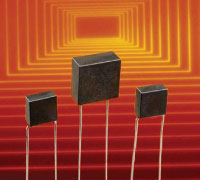
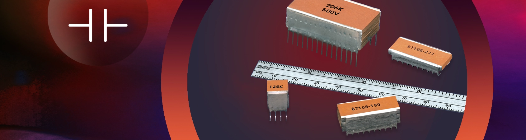
High Temperature Stacked Capacitors for temperatures up to 200°C and feature a Rugged Stack with Hi-Temp Lead-Attachment. These Hi Temp Capacitors have MLC designs for utilizing military grade ceramics.
* Not all combinations create valid part numbers, ask our Apps Engineering Team for assistance creating a valid part number Request for assistance
Click below to see the new Global Part Number Reference Chart for this product
Subfamily
SMPS T-Series - BME
Size Multi-Layer Capacitor (MLCC)
2324
3839
43102
43205
79148
12266
Voltage
Industry Std examples:
6.3V
200V
Special Code
3 numeric values in the voltage field - No "R" in the 3 digits - used for values greater than or equal to 10 Volts
1st two digits are Signiant; third digit denotes number of zeros,
100 = 10 Volts
101 = 100 Volts
402 = 4000 Volts
With "R" in the 3 digits - used for capacitance values less than 10 Volts
R = decimal point.
6R3 = 6.3 Volts
Dielectric Temp Char
Class 1 Temp Compensating
NP0/C0G
Class 2 Hi-Dielectric Constants
BX
X7R
X8R
Miscellaneous
Define in special code
Capacitance
Industry Std examples:
1 pF
15 pF
4,700 pF
+ Alpha Cap Codes
Special Code
3 numeric values in the voltage field - No "R" in the 3 digits - used for values greater than or equal to 10 pF
· 1st two digits are Signiant; third digit denotes number of zeros,
100 = 10 pF
101 = 100 pF
With "R" in the 3 digits - used for capacitance values less than 10pF
R = decimal point.
R75 = 0.75 pF
8R2 = 8.2 pF
Tolerance
NP0 <10pF
±0.05pF
±0.1pF
±0.25pF
±0.5pF
NP0 >10pF
±1%
±2%
±5%
±10%
±20%
X7R
±5%
±10%
±20%
Special Code
Marking
No Mark
EIA Mark
Cap Code & Tol
Special Code
Marking available on 0805 and larger sizes
Termination
Surface Mount
Ni/Sn (RoHS)
Ni/SnPb
Cu/Sn (RoHS)
Cu/SnPb
Polyterm Sn (RoHS)
Polyterm Sn/Pb
Surface Mount
Ni/Au (RoHS)
Pd Ag Strike (RoHS)
Pd/Ag (RoHS)
Pt/Ag (RoHS)
Double dip Pd (RoHS)
Special Code
Special Code
Default Catalog Item
Default for AEC Q200
1st special code
The special code is used to designate special (non-Catalog) performance requirements, testing, or physical dimensions.
(Minimum Nominal cap value = 10 pF NPO, 100 pF X7R) Consult Factory for Sizes & Voltages Not Shown (Standard lead material is nickel) Leads to be on center ±.010"
Dielectric
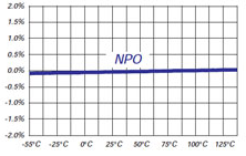
NP0 Dielectric
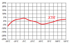
X7R Dielectric
Temperature Coefficient:
0 ± 30ppm/°C, -55 to 125°C
0 ± 30ppm/°C, -55 to 125°C
Cap Drop at 200°C:
minus 0.5% max
minus 45% max
Dissipation Factor:
.001 (0.1%)max, 1Khz, 25°C
.025 (2.5%)max, 1Khz, 25°C
Insulation Resistance: @ 25°C
1000 ΩF or 100 GΩ, whichever is less @ 25°C, WVDC
1000 ΩF or 100 GΩ, whichever is less @ 25°C, WVDC
Insulation Resistance: @ 200°C
1 ΩF or 100 GΩ, whichever is less @ 200°C, WVDC
1 ΩF or 100 GΩ, whichever is less @ 200°C, WVDC
Dielectric Strength:
For 25 - 200 V Ratings:
2.5 X WVDC, 25°C, 500 mA max.
2.5 X WVDC, 25°C, 500 mA max.
For 500 V Ratings:
1.5 X WVDC, 25°C, 500 mA max.
1.5 X WVDC, 25°C, 500 mA max.
For 1 - 4 KV Ratings:
1.2 X WVDC, 25°C, 500 mA max.
1.2 X WVDC, 25°C, 500 mA max.
How to Order
Valid options are shown except for Capacitance
A typical PN is HPEY101G473F3QA001B. This part number breaks down as follows:
New Johanson Global Part Number Breakdown
* Not all combinations create valid part numbers, ask our Apps Engineering Team for assistance creating a valid part number Request for assistance
Click below to see the new Global Part Number Reference Chart for this product
Subfamily
High-Temp Radial 200°
Size Multi-Layer Capacitor (MLCC)
2322
2522
2833
3533
3844
3945
4354
5364
5044
5733
5964
6374
6964
Voltage
Industry Std examples:
6.3V
200V
Special Code
3 numeric values in the voltage field - No "R" in the 3 digits - used for values greater than or equal to 10 Volts
1st two digits are Signiant; third digit denotes number of zeros,
100 = 10 Volts
101 = 100 Volts
402 = 4000 Volts
With "R" in the 3 digits - used for capacitance values less than 10 Volts
R = decimal point.
6R3 = 6.3 Volts
Dielectric Temp Char
Class 1 Temp Compensating
NP0/C0G
Class 2 Hi-Dielectric Constants
BX
X7R
X8R
Miscellaneous
Define in special code
Capacitance
Industry Std examples:
1 pF
15 pF
4,700 pF
+ Alpha Cap Codes
Special Code
3 numeric values in the voltage field - No "R" in the 3 digits - used for values greater than or equal to 10 pF
· 1st two digits are Signiant; third digit denotes number of zeros,
100 = 10 pF
101 = 100 pF
With "R" in the 3 digits - used for capacitance values less than 10pF
R = decimal point.
R75 = 0.75 pF
8R2 = 8.2 pF
Tolerance
NP0 <10pF
±0.05pF
±0.1pF
±0.25pF
±0.5pF
NP0 >10pF
±1%
±2%
±5%
±10%
±20%
X7R
±5%
±10%
±20%
Special Code
Marking
No Mark
EIA Mark
Cap Code & Tol
Special Code
Marking available on 0805 and larger sizes
Termination
Surface Mount
Ni/Sn (RoHS)
Ni/SnPb
Cu/Sn (RoHS)
Cu/SnPb
Polyterm Sn (RoHS)
Polyterm Sn/Pb
Surface Mount
Ni/Au (RoHS)
Pd Ag Strike (RoHS)
Pd/Ag (RoHS)
Pt/Ag (RoHS)
Double dip Pd (RoHS)
Special Code
Special Code
Default Catalog Item
Default for AEC Q200
1st special code
The special code is used to designate special (non-Catalog) performance requirements, testing, or physical dimensions.
Johanson Dielectrics is dedicated to providing the highest level of customer satisfaction through high quality components, superior customer service and forward looking, advanced products.


 1 Lead Length 1.00” [25.40mm] Min
 2 Lead Length 1.50” [38.10mm] Min