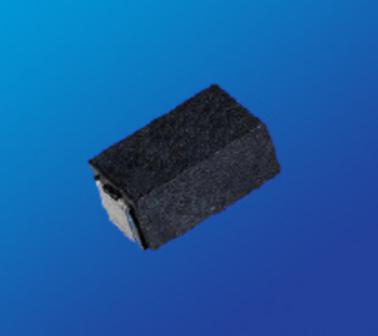
Miniature Axial
| Package Code |
E01 |
E02 |
E03 |
E04 |
E05 |
E06 |
E07 |
E08 |
E09 |
E10 |
E11 |
E12 |
E13 |
| Max Resistance (Ω) 1 |
3.4k |
3.4k |
7.5k |
7.5k |
10k |
10k |
12.5k |
25k |
32k |
50k |
95k |
150k |
260k |
| Max Working Voltage (V) |
33 |
33 |
42 |
42 |
80 |
80 |
135 |
162 |
194 |
258 |
425 |
607 |
1050 |
| Power Rating (W) |
1 |
1 |
1.5 |
1.5 |
2 |
2 |
3 |
4 |
5 |
6 |
7 |
10 |
15 |
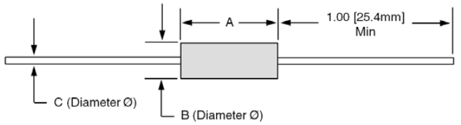
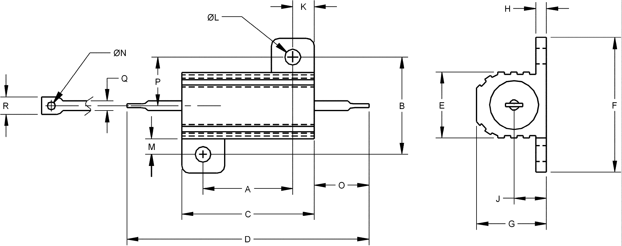
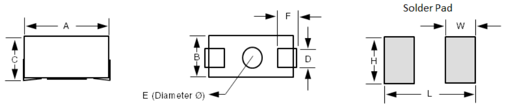
Dimensions
Inches [mm] |
A
±0.062”
[±1.57mm] |
0.250
[6.35] |
0.250
[6.35] |
0.312
[7.92] |
0.312
[7.92] |
0.406
[10.31] |
0.406
[10.31] |
0.350
[8.89] |
0.560
[14.22] |
0.500
[12.70] |
0.625
[15.88] |
0.875
[22.23] |
1.220
[30.99] |
1.780
[45.21] |
B
±0.031”
[±0.79mm] |
0.085
[2.16] |
0.085
[2.16] |
0.078
[1.98] |
0.078
[1.98] |
0.094
[2.39] |
0.094
[2.39] |
0.156
[3.96] |
0.187
[4.75] |
0.218
[5.54] |
0.250
[6.35] |
0.312
[7.92] |
0.312
[7.92] |
0.375
[9.53] |
C 2
±0.002”
[±0.05mm] |
0.020
[0.51] |
0.025
[0.64] |
0.020
[0.51] |
0.025
[0.64] |
0.025
[0.64] |
0.020
[0.51] |
0.032
[0.81] |
0.032
[0.81] |
0.040
[1.02] |
0.040
[1.02] |
0.040
[1.02] |
0.040
[1.02] |
0.040
[1.02] |
MIL-R-26 / MIL-R-39007 |
RW-81
RWR-81 |
RW-81
RWR-81 |
RWR-82 |
RWR-82 |
RW-80
RWR-80 |
RW-80
RWR-80 |
|
|
|
|
RW-84 |
|
|
 1
1 For non-inductive windings / divide maximum resistance by 2
2 Lead Diameter: 18 AWG = 0.040" / 20 AWG = 0.032” / 22 AWG = 0.025" / 24 AWG = 0.020"
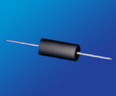
Axial
| Package Code |
F01 |
F02 |
F03 |
F04 |
F05 |
F06 |
F07 |
F08 |
F09 |
F10 |
F11 |
| Max Resistance (Ω) 1 |
500 |
2.5k |
2.5k |
7.5k |
7.5k |
10k |
10k |
12.5k |
22k |
22k |
40k |
| Max Working Voltage (V) |
8.5 |
20 |
20 |
29 |
29 |
52 |
52 |
60 |
130 |
140 |
140 |
Power Rating (W) |
U |
0.1 |
0.4 |
0.4 |
0.75 |
0.75 |
1.0 |
1.0 |
1.5 |
2.5 |
3.0 |
3.0 |
| V |
0.25 |
0.5 |
0.5 |
0.9 |
0.9 |
1.5 |
1.5 |
2.0 |
3.0 |
3.75 |
4.0 |
Dimensions
Inches [mm] |
A
±0.062”
[±1.57mm] |
0.150
[3.81] |
0.250
[6.35] |
0.250
[6.35] |
0.330
[8.38] |
0.330
[8.38] |
0.406
[10.31] |
0.406
[10.31] |
0.350
[8.89] |
0.500
[12.70] |
0.560
[14.22] |
0.500
[12.70] |
B
±0.031”
[±0.79mm] |
0.094
[2.39] |
0.085
[2.16] |
0.094
[2.39] |
0.094
[2.39] |
0.094
[2.39] |
0.094
[2.39] |
0.094
[2.39] |
0.156
[3.96] |
0.187
[4.75] |
0.187
[4.75] |
0.250
[6.35] |
C 2
±0.002”
[±0.05mm] |
0.018
[0.45] |
0.020
[0.51] |
0.025
[0.64] |
0.020
[0.51] |
0.025
[0.64] |
0.020
[0.51] |
0.025
[0.64] |
0.032
[0.81] |
0.032
[0.81] |
0.032
[0.81] |
0.040
[1.02] |
| MIL-R-26 / MIL-R-39007 |
|
|
|
|
|
RW-70 |
RW-70 |
|
RW-69 |
RW-79 |
|
| Package Code |
F12 |
F13 |
F14 |
F15 |
F16 |
F17 |
F18 |
F19 |
F20 |
F21 |
F22 |
F23 |
| Max Resistance (Ω) 1 |
40k |
30k |
45k |
45k |
91k |
65k |
95k |
150k |
100k |
154k |
260k |
320k |
| Max Working Voltage (V) |
140 |
140 |
210 |
210 |
360 |
390 |
504 |
650 |
590 |
620 |
850 |
1500 |
Power Rating (W) |
U |
3.0 |
3.0 |
4.0 |
4.0 |
5.0 |
5.0 |
5.0 |
7.0 |
7.0 |
7.0 |
10 |
15 |
| V |
4.0 |
3.5 |
5.5 |
5.5 |
6.5 |
6.5 |
6.5 |
9.0 |
9.0 |
9.0 |
13 |
- |
Dimensions
Inches [mm] |
A
±0.062”
[±1.57mm] |
0.500
[12.70] |
0.500
[12.70] |
0.675
[17.15] |
0.675
[17.15] |
0.875
[22.23] |
0.970
[24.64] |
1.025
[26.04] |
1.375
[34.93] |
1.400
[35.56] |
1.200
[30.99] |
1.780
[45.21] |
1.810
[45.95] |
B
±0.031”
[±0.79mm] |
0.250
[6.35] |
0.200
[5.08] |
0.270
[6.68] |
0.270
[6.68] |
0.312
[7.92] |
0.250
[6.35] |
0.312
[7.92] |
0.375
[9.52] |
0.312
[7.92] |
0.312
[7.92] |
0.375
[9.52] |
0.510
[12.95] |
C 2
±0.002”
[±0.05mm] |
0.032
[0.81] |
0.032
[0.81] |
0.040
[1.02] |
0.032
[0.81] |
0.040
[1.02] |
0.032
[0.81] |
0.040
[1.02] |
0.040
[1.02] |
0.032
[0.81] |
0.040
[1.02] |
0.040
[1.02] |
0.050
[1.27] |
| MIL-R-26 / MIL-R-39007 |
|
|
|
|
RW-74 |
|
RW-67 |
|
|
|
RW-78 |
|
1 For non-inductive windings / divide maximum resistance by 2
2 Lead Diameter: 18 AWG = 0.040" / 20 AWG = 0.032” / 22 AWG = 0.025" /
24 AWG = 0.020" / 25 AWG = 0.018"
Environmental Performance
|
 R R |
Environmental Performance
(MIL-STD 202) |
Miniature Axial |
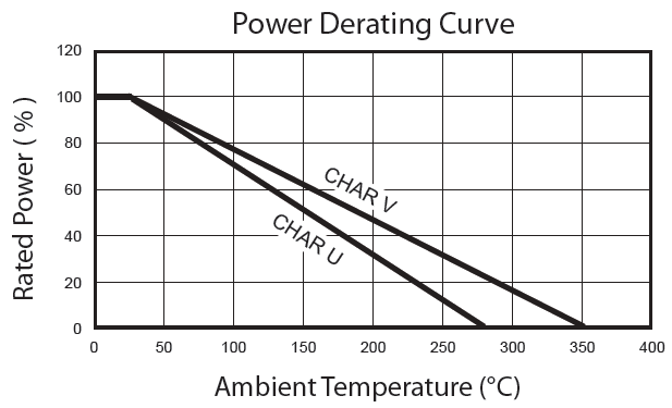
Axial - Characteristic U |
Axial - Characteristic V |
| Vibration |
±0.1 % + 0.05 Ω |
±0.1% + 0.05 Ω |
±0.2% + 0.05 Ω |
Load Life |
To 1% Depending on
Resistance Value and Size |
±0.1% + 0.05 Ω |
±3% + 0.05 Ω |
| Moisture Resistance |
±0.2 % + 0.05 Ω |
±0.2% + 0.05 Ω |
±2% + 0.05 Ω |
| Dielectric |
±0.2 % + 0.05 Ω |
±0.2% + 0.05 Ω |
±0.2% + 0.05 Ω |
| Storage |
±0.2 % + 0.05 Ω |
±0.2% + 0.05 Ω |
±0.2% + 0.05 Ω |
| Shock |
±0.2 % + 0.05 Ω |
±0.1% + 0.05 Ω |
±0.2% + 0.05 Ω |
| Thermal Shock |
±0.2 % + 0.05 Ω |
±0.2% + 0.05 Ω |
±0.2% + 0.05 Ω |
| 5X Overload (5s) |
±0.2 % + 0.05 Ω |
±0.2% + 0.05 Ω |
±0.2% + 0.05 Ω |
- Centerless ground ceramic core
- Tinned copper or copperweld leads
- All welded terminations
- High Temperature / trivalent / inorganic silicone coating
Packaging Information
MINIATURE AXIAL: Bulk Only
Axial:
| Package Code |
F01 |
F02 |
F03 |
F04 |
F05 |
F06 |
F07 |
F08 |
F09 |
F10 |
F11 |
F12 |
F13 |
F14 |
F15 |
F16 |
F17 |
F18 |
F19 |
F20 |
F21 |
F22 |
| Bulk |
Bulk
Only.
No T&R |
1000 |
1000 |
1000 |
1000 |
1000 |
1000 |
1000 |
1000 |
1000 |
1000 |
1000 |
1000 |
1000 |
1000 |
1000 |
1000 |
1000 |
1000 |
1000 |
1000 |
1000 |
| 10" Reel |
2000 |
2000 |
2000 |
2000 |
2000 |
2000 |
2000 |
500 |
500 |
500 |
500 |
500 |
N/A |
N/A |
N/A |
500 |
N/A |
N/A |
N/A |
N/A |
N/A |
| 12" Reel |
3000 |
3000 |
3000 |
3000 |
3000 |
3000 |
3000 |
1500 |
1500 |
1000 |
1000 |
1000 |
500 |
500 |
500 |
1000 |
500 |
500 |
500 |
500 |
500 |
| 14" Reel |
5000 |
5000 |
5000 |
5000 |
5000 |
5000 |
5000 |
3000 |
3000 |
1500 |
1500 |
1500 |
1000 |
1000 |
1000 |
1500 |
1000 |
750 |
750 |
750 |
750 |
* Moisture Sensitivity Level: MSL-1
Available Options (Consult Factory)
- Special Testing Requirements
- Special Pulse Requirements
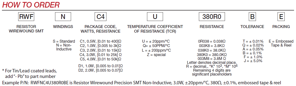
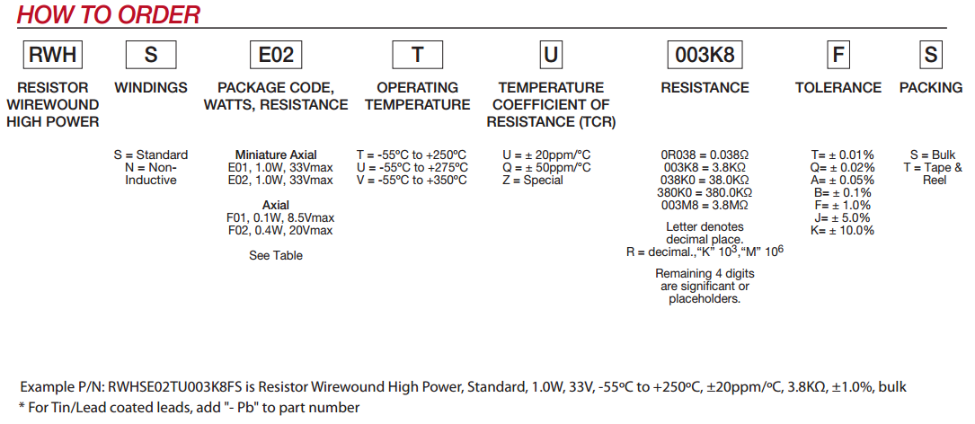
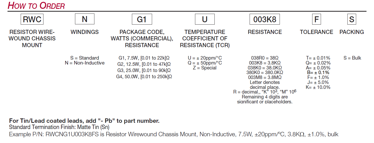
How to Order


 R±0.05%
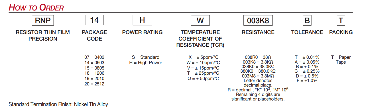

 Lead Thickness 0.006 [.015mm] Tolerances ±0.002” [±0.05mm]