High Temp Rated Radial Leaded MLCC 200°C
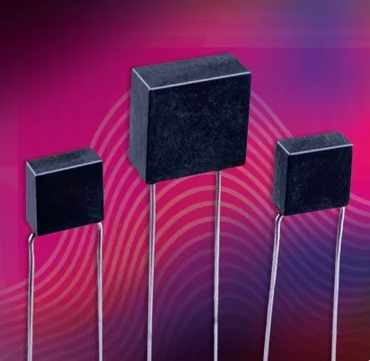
200°C Radial Leaded MLCCs for Downhole, Geophysical, and Jet Engine Electronics
Features:
- Withstands Operating Temperature Up to 200°C
- Dielectric Type: NP0, X7R
- Capacitance Range: 200pF-3.9uF
- Rated Working Voltages from 50V to 4KV
- Rugged Premolded Case with Hi-Temp Epoxy Fill
- Compact MLC Designs Utilizing Military Grade Ceramics
- Custom Sizes, Values, and Voltages Available
Common Applications:
- Oil Well Logging (Down-hole)
- Geophysical Probes
- Jet Engine Controls
Capacitance and Voltage Selection
| Code Legacy |
Version EIA Size |
T | W | H | S | d Dia. | Maximum Capacitance | ||||||||||
|---|---|---|---|---|---|---|---|---|---|---|---|---|---|---|---|---|---|
| (±.005") | (+/-.030") | (+/-.002") | 25V | 50V | 100V | 200V | 500V | 1KV | 2KV | 3KV | 4KV | ||||||
| DH T2A |
003 1316 |
in | 0.100 | 0.200 | 0.200 | 0.100 | 0.020 | NPO | 223 | 153 | 902 | 502 | 302 | 152 | 561 | 221 | 560 |
| mm | (2.54) | (5.08) | (5.08) | (2.54) | (0.51) | X7R | 334 | 224 | 124 | 563 | 303 | 103 | 262 | 391 | 121 | ||
| DH T2B |
004 1316 |
in | 0.100 | 0.200 | 0.200 | 0.170 | 0.020 | NPO | 223 | 153 | 902 | 502 | 302 | 152 | 561 | 221 | 560 |
| mm | (2.54) | (5.08) | (5.08) | (4.32) | (0.51) | X7R | 334 | 224 | 124 | 563 | 303 | 103 | 262 | 391 | 121 | ||
| DH T2C |
005 1316 |
in | 0.100 | 0.200 | 0.200 | 0.200 | 0.020 | NPO | 223 | 153 | 902 | 502 | 302 | 152 | 561 | 221 | 560 |
| mm | (2.54) | (5.08) | (5.08) | (5.08) | (0.51) | X7R | 334 | 224 | 124 | 563 | 303 | 103 | 262 | 391 | 121 | ||
| EK T3A |
003 2322 |
in | 0.100 | 0.300 | 0.300 | 0.200 | 0.020 | NPO | 603 | 503 | 283 | 163 | 103 | 682 | 222 | 102 | 301 |
| mm | (2.54) | (7.62) | (7.62) | (5.08) | (0.51) | X7R | 105 | 105 | 394 | 224 | 104 | 123 | 472 | 102 | 221 | ||
| EK T3B |
004 2322 |
in | 0.150 | 0.300 | 0.300 | 0.200 | 0.020 | NPO | 823 | 623 | 423 | 343 | 203 | 133 | 432 | 222 | 561 |
| mm | (3.81) | (7.62) | (7.62) | (5.08) | (0.51) | X7R | 563 | 125 | 824 | 464 | 214 | 563 | 203 | 332 | 102 | ||
| ET T3C |
003 2522 |
in | 0.250 | 0.320 | 0.300 | 0.200 | 0.020 | NPO | 823 | 683 | 483 | 373 | 273 | 183 | 822 | 362 | 102 |
| mm | (6.35) | (8.13) | (7.62) | (5.08) | (0.51) | X7R | 155 | 155 | 904 | 624 | 404 | 124 | 393 | 822 | 222 | ||
| EY T3D |
003 2833 |
in | 0.275 | 0.350 | 0.400 | 0.300 | 0.020 | NPO | 124 | 104 | 803 | 623 | 503 | 333 | 153 | 562 | 152 |
| mm | (6.99) | (8.89) | (10.16) | (7.62) | (0.51) | X7R | 225 | 225 | 165 | 105 | 724 | 274 | 732 | 153 | 472 | ||
| FJ T4A |
003 3533 |
in | 0.250 | 0.420 | 0.400 | 0.300 | 0.025 | NPO | 154 | 124 | 104 | 683 | 563 | 393 | 163 | 103 | 272 |
| mm | (6.35) | (10.67) | (10.16) | (7.62) | (0.64) | X7R | 335 | 305 | 205 | 125 | 724 | 334 | 753 | 223 | 562 | ||
| FT T4B |
004 3844 |
in | 0.300 | 0.450 | 0.500 | 0.300 | 0.025 | NPO | 244 | 224 | 164 | 124 | 783 | 563 | 293 | 103 | 392 |
| mm | (7.62) | (11.43) | (12.7) | (7.62) | (0.64) | X7R | 445 | 405 | 305 | 205 | 125 | 564 | 144 | 333 | 103 | ||
| FX T5A |
003 3945 |
in | 0.100 | 0.500 | 0.500 | 0.400 | 0.025 | NPO | 334 | 184 | 104 | 683 | 413 | 273 | 682 | 392 | 152 |
| mm | (2.54) | (12.7) | (12.7) | (10.16) | (0.64) | X7R | 475 | 405 | 125 | 724 | 404 | 104 | 333 | 822 | 222 | ||
| FX T5B |
004 3945 |
in | 0.150 | 0.500 | 0.500 | 0.400 | 0.025 | NPO | 304 | 254 | 184 | 124 | 803 | 473 | 103 | 822 | 222 |
| mm | (3.81) | (12.7) | (12.7) | (10.16) | (0.64) | X7R | 555 | 505 | 335 | 155 | 724 | 224 | 683 | 203 | 562 | ||
| FX T5C |
005 3945 |
in | 0.200 | 0.500 | 0.500 | 0.400 | 0.025 | NPO | 304 | 254 | 184 | 144 | 104 | 683 | 223 | 123 | 332 |
| mm | (5.08) | (12.7) | (12.7) | (10.16) | (0.64) | X7R | 555 | 505 | 275 | 225 | 105 | 394 | 104 | 303 | 103 | ||
| FX T5D |
006 3945 |
in | 0.250 | 0.500 | 0.500 | 0.400 | 0.025 | NPO | 304 | 254 | 184 | 144 | 104 | 823 | 273 | 153 | 392 |
| mm | (6.35) | (12.7) | (12.7) | (10.16) | (0.64) | X7R | 555 | 505 | 275 | 225 | 105 | 474 | 104 | 223 | 103 | ||
| FX T5E |
007 345 |
in | 0.300 | 0.520 | 0.500 | 0.400 | 0.025 | NPO | 304 | 254 | 224 | 154 | 104 | 823 | 333 | 153 | 492 |
| mm | (7.62) | (13.21) | (12.7) | (10.16) | (0.64) | X7R | 555 | 505 | 275 | 225 | 105 | 564 | 154 | 473 | 153 | ||
| GD T5F |
003 4354 |
in | 0.400 | 0.600 | 0.700 | 0.500 | 0.025 | NPO | 424 | 324 | 224 | 184 | 124 | 104 | 563 | 203 | 822 |
| mm | (10.16) | (15.24) | (17.78) | (12.7) | (0.64) | X7R | 625 | 445 | 405 | 305 | 225 | 105 | 274 | 683 | 222 | ||
| HJ T6A |
003 5364 |
in | 0.375 | 0.650 | 0.700 | 0.600 | 0.025 | NPO | 564 | 484 | 334 | 224 | 204 | 154 | 823 | 333 | 153 |
| mm | (9.53) | (16.51) | (17.78) | (15.24) | (0.64) | X7R | 106 | 805 | 525 | 485 | 305 | 125 | 474 | 124 | 333 | ||
| HB T6B |
003 5044 |
in | 0.300 | 0.620 | 0.500 | 0.500 | 0.025 | NPO | 394 | 304 | 224 | 184 | 124 | 104 | 563 | 223 | 103 |
| mm | (7.62) | (15.75) | (12.7) | (12.7) | (0.64) | X7R | 705 | 605 | 405 | 305 | 205 | 684 | 274 | 683 | 183 | ||
| HQ T7A |
003 5733 |
in | 0.200 | 0.700 | 0.400 | 0.500 | 0.025 | NPO | 334 | 274 | 184 | 154 | 114 | 823 | 333 | 153 | 472 |
| mm | (5.08) | (17.78) | (10.16) | (12.7) | (0.64) | X7R | 625 | 505 | 335 | 255 | 125 | 474 | 154 | 393 | 103 | ||
| HT T7B |
003 5964 |
in | 0.300 | 0.720 | 0.700 | 0.600 | 0.025 | NPO | 684 | 504 | 404 | 304 | 224 | 184 | 823 | 393 | 183 |
| mm | (7.62) | (18.29) | (17.78) | (15.24) | (0.64) | X7R | 126 | 106 | 725 | 565 | 335 | 125 | 474 | 124 | 333 | ||
| JD T7C |
003 6374 |
in | 0.375 | 0.750 | 0.800 | 0.700 | 0.025 | NPO | 684 | 564 | 474 | 394 | 294 | 274 | 124 | 473 | 273 |
| mm | (9.53) | (19.05) | (20.32) | (17.78) | (0.64) | X7R | 156 | 126 | 985 | 625 | 425 | 225 | 684 | 224 | 473 | ||
| JJ T8A |
004 6964 |
in | 0.350 | 0.820 | 0.700 | 0.700 | 0.025 | NPO | 624 | 564 | 474 | 374 | 284 | 224 | 124 | 473 | 273 |
| mm | (8.89) | (20.83) | (17.78) | (17.78) | (0.64) | X7R | 126 | 106 | 825 | 565 | 405 | 225 | 684 | 224 | 473 | ||
(Minimum Nominal cap value = 10 pF NPO, 100 pF X7R)
Consult Factory for Sizes & Voltages Not Shown (Standard lead material is nickel)
Leads to be on center ±.010"
Dielectric
| NP0 Dielectric | X7R Dielectric | |
|---|---|---|
| Temperature Coefficient: | 0 ± 30ppm/°C, -55 to 125°C | +/- 15% -55 to +125C |
| Cap Drop at 200°C: | minus 0.5% max | minus 45% max |
| Dissipation Factor: | .001 (0.1%)max, 1Khz, 25°C | .025 (2.5%)max, 1Khz, 25°C |
| Insulation Resistance: @ 25°C | 1000 ΩF or 100 GΩ, whichever is less @ 25°C, WVDC | 1000 ΩF or 100 GΩ, whichever is less @ 25°C, WVDC |
| Insulation Resistance: @ 200°C | 1 ΩF or 100 GΩ, whichever is less @ 200°C, WVDC | 1 ΩF or 100 GΩ, whichever is less @ 200°C, WVDC |
| Dielectric Strength: | ||
| For 25 - 200 V Ratings: | 2.5 X WVDC, 25°C, 500 mA max. | 2.5 X WVDC, 25°C, 500 mA max. |
| For 500 V Ratings: | 1.5 X WVDC, 25°C, 500 mA max. | 1.5 X WVDC, 25°C, 500 mA max. |
| For 1 - 4 KV Ratings: | 1.2 X WVDC, 25°C, 500 mA max. | 1.2 X WVDC, 25°C, 500 mA max. |
MLC General Specifications:
- Rated Voltage: 50V - 4KV
- Dielectrics Type: NP0, X7R
- Capacitance Range: 220 pF - 3.9 μF
Key Features of the High Temperature Capacitor:
- For Use at Temperatures Up to 200°C
- Rated Working Voltages from 50V to 4KV
- Rugged Premolded Case with Hi-Temp Epoxy Fill
- Compact MLC Designs Utilizing Military Grade Ceramics
- Custom Sizes, Values, and Voltages Available
Key Features of the High Temperature Capacitor:
- Oil Well Logging (Downhole)
- Geophysical Probes
- Jet Engine Controls
How to Order
Valid options are shown except for Capacitance
A typical PN is HPEY102G223MZQA001B. This part number breaks down as follows:
HPEY102G223MZQA001B Capacitors High-Temperature Radial 200°, 2833, NP0/C0G, 1,000.0V, 0.022µF±20%, Black Composite Case w/ Radial Wire (Ni/SnPb), Bulk
New Johanson Global Part Number Breakdown
* Not all combinations create valid part numbers, ask our Apps Engineering Team for assistance creating a valid part number Request for assistanceClick below to see the new Global Part Number Reference Chart for this product
The legacy info below is for reference only.
Johanson has instituted a new Global Part Numbering (GPN) system.
Only the part number is changing. The parts are produced with the exact same materials, manufacturing processes, manufacturing controls, dimensions, physical attributes and testing as the parts supplied with the legacy part numbers.
The GPNs will be phased in over the next several years and are planned to be completed by January 1, 2026.
We will continue to quote and accept orders with the current (legacy) part numbers throughout this period.
Beginning January 1, 2022, all samples will be provided with the GPN.
Updates associated with this change will occur periodically.
A database for the approximate 2 million crosses can be accessed at: https://www.johansontechnology.com/pn-search
